Installation – Wavetronix Click 400 (900 MHz radio) (CLK-400) - User Guide User Manual
Page 178

CHAPTER 20 • CLICK 223
177
˽
Two RS-485 connections, each consisting of one -485 and one +485 terminal
The front of the Click 223 has an LED that lights up to indicate the device has power and the
surge protection is working properly. If the LED is not lit, either the device has no power or
the surge protection is not working.
Installation
The Click 223 is designed for use with the SmartSensor 6-conductor cable and a Wavetronix
sensor that uses this cable, such as the SmartSensor Advance. The steps that follow in this
section are specific to this application. If you do not plan on using the 6-conductor cable,
you can skip the steps below and simply wire your power and communications by following
the labels on the screw terminals.
Which side of the Click 223 you wire into depends on your installation. If you’ve got an un-
derground cable run, you’ll put a Click 223 on each end and connect the ends of the cable to
the UNPROTECTED side of each device. If you’re connecting to a sensor as well, the sensor
cable should be connected into the side of the device marked PROTECTED.
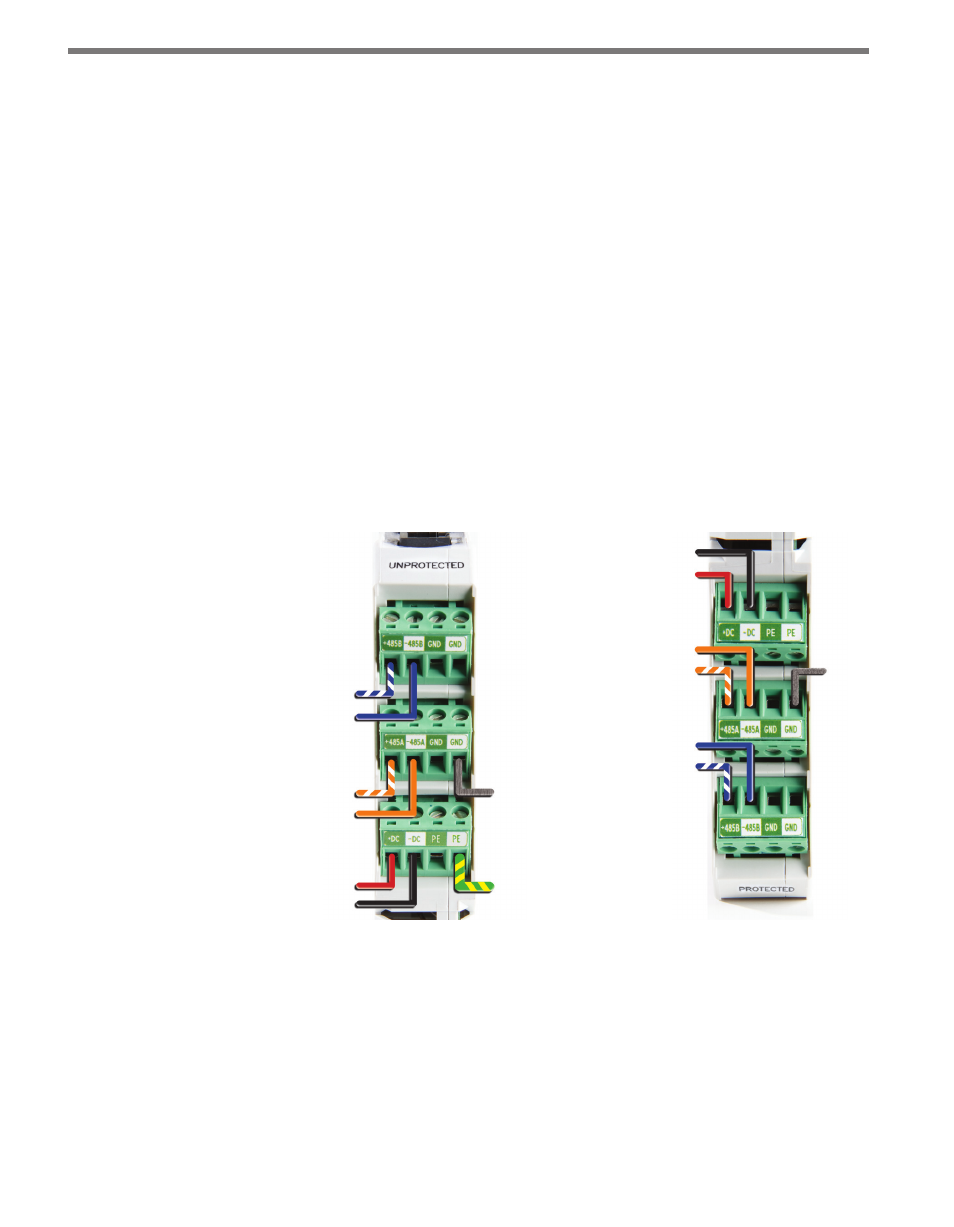
+485B (Blue/white)
-485B (Blue)
-485A (Orange)
+485A (Orange/white)
+DC (Red)
-DC (Black)
Earth ground
Drain
Drain
+485B (Blue/white)
-485B (Blue)
-485A (Orange)
+485A (Orange/white)
+DC (Red)
-DC (Black)
Figure 20.3 – Wiring the Click 223
Once you know which side of the device you need to wire into, follow the steps below to
do so:
1 Using a rocking motion, mount the Click 223 onto the DIN rail, making sure it’s on the
T-bus with the devices it’s supposed to protect.
2 Wire the cable to the frontmost pluggable screw terminal block: connect the blue wire
to the screw terminal marked -485B. Connect the blue and white–striped wire to the
screw terminal marked +485B. (For ease, you can remove the terminal block from the
- Click 421 (bluetooth to serial converter) (CLK-421) - User Guide Click 342 (lean managed ethernet switch) (CLK-342) - User Guide Click 341 (lean managed ethernet switch) (CLK-341) - User Guide Click 340 (lean managed ethernet switch) (CLK-340) - User Guide Click 331 (unmanaged ethernet switch) (CLK-331) - User Guide Click 330 (unmanaged ethernet switch) (CLK-330) - User Guide Click 304 (RS-232 to RS-485 converter) (CLK-304) - User Guide Click 305 (RS-232 to RS-485 converter) (CLK-305) - User Guide Click 301 (serial to ethernet converter) (CLK-301) - User Guide Click 100 (16 output contact closure) (CLK-100) - User Guide Click 104 (4-channel DIN rail contact closure) (CLK-104) - User Guide Click 110 (4-channel contact closure eurocard) (CLK-110) - User Guide Click 112 (detector rack card) (CLK-112) - User Guide Click 114 (detector rack card) (CLK-114) - User Guide Click 120 (screw terminal relay) (CLK-120) - User Guide Click 121 (spring cage relay) (CLK-121) - User Guide Click 200 (surge suppression) (CLK-200) - User Guide Click 201 (1 amp AC to DC converter) (CLK-201) - User Guide Click 202 (2 amp AC to DC converter) (CLK-202) - User Guide Click 203 (UPS and battery) (CLK-203) - User Guide Click 204 (4 amp AC to DC converter) (CLK-204) - User Guide Click 210 (AC circuit breaker) (CLK-210) - User Guide Click 211 (AC outlet) (CLK-211) - User Guide Click 221 (DC surge protector) (CLK-221) - User Guide Click 222 (system surge protector) (CLK-222) - User Guide Click 223 (dual-485 surge protector) (CLK-223) - User Guide Click 230 (AC surge protector) (CLK-230) - User Guide Click 250 (wireless surge protector) (CLK-250) - User Guide
