Wiring the click 211 – Wavetronix Click 400 (900 MHz radio) (CLK-400) - User Guide User Manual
Page 167

166
CHAPTER 17 • CLICK 211
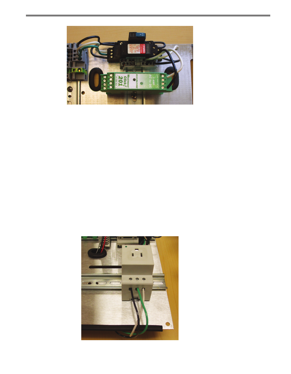
Figure 17.4 – Wiring into the Power Supply
8 Wire power out of the Click 201/202/204 as described in Chapter 1.
Wiring the Click 211
1 Attach a 14 AWG wire that is stripped 3/8” on both ends (green is standard) to the
screw terminal marked G on the OUT side of the Click 230.
2 Attach 14 AWG wires that are stripped 3/8” on both ends to the last set of ports on the
two twin terminal blocks, following the coloring of the wires attached to each block.
3 Snap the Click 211 onto a DIN rail within reaching distance of the device to be plugged
in. The device cannot be mounted over a T-bus.
4 Terminate the line (black) wire into the screw terminal on the Click 211 marked L1.
5 Terminate the ground (green) wire into the screw terminal on the Click 211 marked
PE (protective earth).
6 Terminate the neutral (white) wire into the screw terminal on the Click 211 marked N
(see Figure 17.5).
Figure 17.5 – Properly Wired Click 211
- Click 421 (bluetooth to serial converter) (CLK-421) - User Guide Click 342 (lean managed ethernet switch) (CLK-342) - User Guide Click 341 (lean managed ethernet switch) (CLK-341) - User Guide Click 340 (lean managed ethernet switch) (CLK-340) - User Guide Click 331 (unmanaged ethernet switch) (CLK-331) - User Guide Click 330 (unmanaged ethernet switch) (CLK-330) - User Guide Click 304 (RS-232 to RS-485 converter) (CLK-304) - User Guide Click 305 (RS-232 to RS-485 converter) (CLK-305) - User Guide Click 301 (serial to ethernet converter) (CLK-301) - User Guide Click 100 (16 output contact closure) (CLK-100) - User Guide Click 104 (4-channel DIN rail contact closure) (CLK-104) - User Guide Click 110 (4-channel contact closure eurocard) (CLK-110) - User Guide Click 112 (detector rack card) (CLK-112) - User Guide Click 114 (detector rack card) (CLK-114) - User Guide Click 120 (screw terminal relay) (CLK-120) - User Guide Click 121 (spring cage relay) (CLK-121) - User Guide Click 200 (surge suppression) (CLK-200) - User Guide Click 201 (1 amp AC to DC converter) (CLK-201) - User Guide Click 202 (2 amp AC to DC converter) (CLK-202) - User Guide Click 203 (UPS and battery) (CLK-203) - User Guide Click 204 (4 amp AC to DC converter) (CLK-204) - User Guide Click 210 (AC circuit breaker) (CLK-210) - User Guide Click 211 (AC outlet) (CLK-211) - User Guide Click 221 (DC surge protector) (CLK-221) - User Guide Click 222 (system surge protector) (CLK-222) - User Guide Click 223 (dual-485 surge protector) (CLK-223) - User Guide Click 230 (AC surge protector) (CLK-230) - User Guide Click 250 (wireless surge protector) (CLK-250) - User Guide
