Physical features, Installation – Wavetronix Click 400 (900 MHz radio) (CLK-400) - User Guide User Manual
Page 165

164
CHAPTER 17 • CLICK 211
Note
Wiring the Click 211 from the power plant requires the use of two twin terminal blocks.
Physical Features
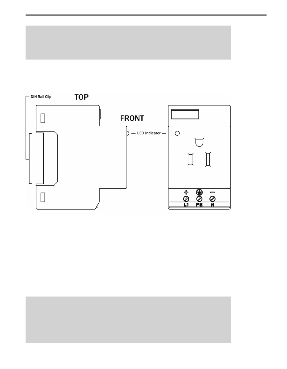
Figure 17.2 – Diagram of the Click 211
The Click 211 has three screw terminal connections, located on the top of the module, for
wiring in power. There is also an LED located on the front of the module; this LED lights up
when the Click 211 is working properly.
Installation
Installing the Click 211 involves a slight change in how your installation’s power plant is put
together. Follow these steps to wire the power plant and Click 211.
Note
The pictures below show the Click 211 being installed on a backplate as part of a cabi-
net installation. It is not necessary to use a backplate, however, and if you are not,
the wiring will still be the same.
- Click 421 (bluetooth to serial converter) (CLK-421) - User Guide Click 342 (lean managed ethernet switch) (CLK-342) - User Guide Click 341 (lean managed ethernet switch) (CLK-341) - User Guide Click 340 (lean managed ethernet switch) (CLK-340) - User Guide Click 331 (unmanaged ethernet switch) (CLK-331) - User Guide Click 330 (unmanaged ethernet switch) (CLK-330) - User Guide Click 304 (RS-232 to RS-485 converter) (CLK-304) - User Guide Click 305 (RS-232 to RS-485 converter) (CLK-305) - User Guide Click 301 (serial to ethernet converter) (CLK-301) - User Guide Click 100 (16 output contact closure) (CLK-100) - User Guide Click 104 (4-channel DIN rail contact closure) (CLK-104) - User Guide Click 110 (4-channel contact closure eurocard) (CLK-110) - User Guide Click 112 (detector rack card) (CLK-112) - User Guide Click 114 (detector rack card) (CLK-114) - User Guide Click 120 (screw terminal relay) (CLK-120) - User Guide Click 121 (spring cage relay) (CLK-121) - User Guide Click 200 (surge suppression) (CLK-200) - User Guide Click 201 (1 amp AC to DC converter) (CLK-201) - User Guide Click 202 (2 amp AC to DC converter) (CLK-202) - User Guide Click 203 (UPS and battery) (CLK-203) - User Guide Click 204 (4 amp AC to DC converter) (CLK-204) - User Guide Click 210 (AC circuit breaker) (CLK-210) - User Guide Click 211 (AC outlet) (CLK-211) - User Guide Click 221 (DC surge protector) (CLK-221) - User Guide Click 222 (system surge protector) (CLK-222) - User Guide Click 223 (dual-485 surge protector) (CLK-223) - User Guide Click 230 (AC surge protector) (CLK-230) - User Guide Click 250 (wireless surge protector) (CLK-250) - User Guide
