3 remote connector and pinouts 2.3.4 connector, Table 14. remote connector and pinouts – Comtech EF Data CDM-IP 300L User Manual
Page 68
CDM-IP 300L IP-Centric Satellite Modem
Rev. 1
CD/CDMIP300L.IOM
41
2.3.3 R
EMOTE
C
ONNECTOR AND
P
INOUTS
The remote connector is a 9-pin subminiature male D connector (J6) located on the rear
panel of the modem. Screw locks are provided for mechanical security of the mating
connector.
The remote connector interfaces the M & C functions to a remote location. The remote
location can be an M&C computer located away from the modem, but attached via cable
to the remote connector. This DCE interface is user selectable for either RS-232 or RS-
485.
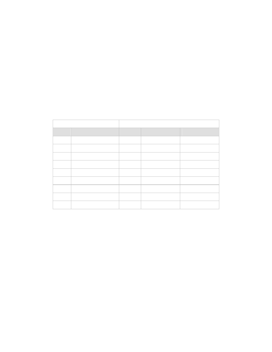
Table 14. Remote Connector and Pinouts
RS-232
RS-485
Pin #
Name
Pin #
Name (2-Wire)
Name (4-Wire)
1
1 GND
GND
2 RD
(RX)
2
3 TD
(TX)
3
4
4* +RX/TX
+TX
5 GND
5* -RX/TX
-TX
6 DSR
6
7 RTS
7
8 CTS
8* +RX/TX
+RX
9
9* -RX/TX
-RX
Note: *For 2-Wire Operation:
1 Only two wires are required.
2 Tie pins 4 and 8 together (both +).
3 Tie pins 5 and 9 together (both -).
2.3.4 C
ONNECTOR
(J6)
J6 connector is not used at this time.