Table 2. modulation specifications – Comtech EF Data CDM-IP 300L User Manual
Page 52
CDM-IP 300L IP-Centric Satellite Modem
Rev. 1
CD/CDMIP300L.IOM
24
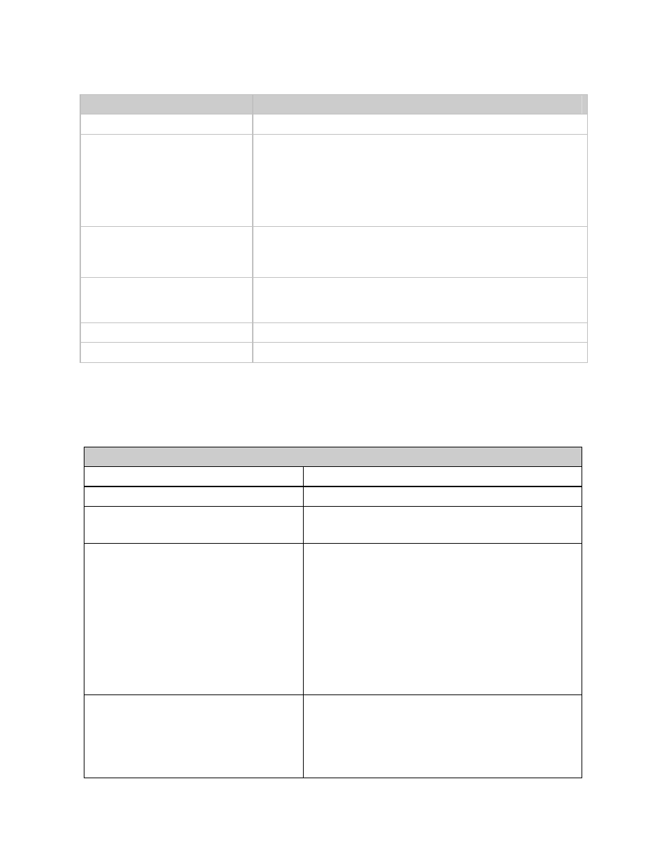
Parameter
Description
Prime Power
85 to 264 VAC, 47 to 63 Hz, 60 Watts maximum
Physical:
Size
Weight
Mounting
1 RU1.75H x 19W x 19.18D inches (4.44 x 48.26 x 48.72 cm)
14.5 lbs. Maximum (6.51 kg)
Standard 19-inch (48.62 cm) rack mounts front and rear accepts
standard rack mount slides (no slides with 150W BUC power
supply option)
Environmental:
Temperature
Humidity
0 to +50°C (32 to 122°F)
95% non-condensing
Operational Shock
MIL-STD-167-1. When any one corner of the modem is dropped
from 1 cm onto a hard surface, the modem will not take any errors
or faults.
Survivability Shock and Vibration MIL-STD-810D Method 514.4, Procedure 8, 1 hour/axis
Agency Approvals
CE Mark
Table 2. Modulation Specifications
Transmit Specifications
Output Connector
Type N Female
Output Frequency
950 to 1750 MHz in 100 Hz steps
Frequency Stability
± 0.02 ppm
Optional:
± 1.0 ppm
External Reference Input (Standard)
The External frequency reference connector is located
on the back panel. This allows the Frequency
Reference to be locked to an external reference
frequency standard.
Impedance 75
Ω
Frequency
1, 5, 10 or 20 MHz (10 MHz required if
supplying 10 MHz reference to BUC or LNB)
Amplitude
≥ +0 dBm < +20 dBm
DC offset
Capacitively coupled
Connector
BNC female (50
Ω)
Reference Frequency Output
The External frequency reference connector can be
used as an output. When selected from the front
panel, this output can be used to lock other equipment
to the Internal High Stability Reference of the selected
modem.
The output is 10 MHz, the level is +5
± 5 dBm.