Figure 2. router mode, point-to-point diagram – Comtech EF Data CDM-IP 300L User Manual
Page 35
CDM-IP 300L IP-Centric Satellite Modem
Rev. 1
CD/CDMIP300L.IOM
7
10
/100
Bas
eT
L
A
N
10
.20.
1.0 /
16
10/1
00 Base
T
L
A
N
10.1
0.1
.0 /1
6
Satellite
Satellite dish
25
6
kb
ps
TX
Hub CDM-IP 1
(efi0) 10.10.1.1/16
Satellite dish
25
6
kb
ps
Remote CDM-IP 2
(efi0) 10.20.1.1/16
PC
IP 10.10.1.100/16
GW 10.10.1.1
PC
IP 10.20.1.100/16
GW 10.20.1.1
TX
RX
RX
Static Routes
IP Dest
Next Hop
Type
10.20.0.0/16 Point-to-Point ToSat
Static Routes
IP Dest
Next Hop
Type
10.10.0.0/16 Point-to-Point ToSat
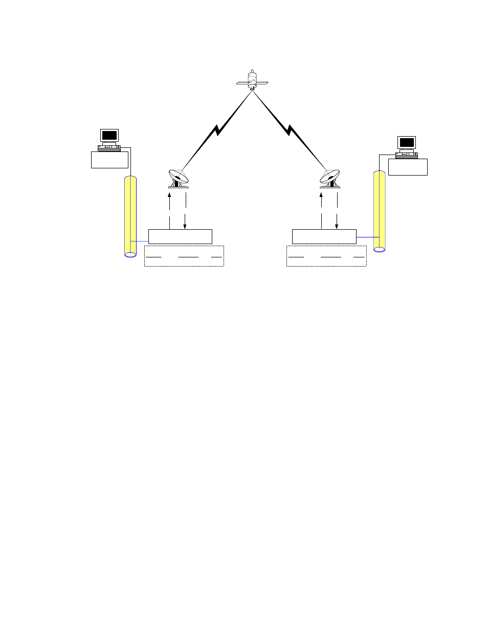
Figure 2. Router Mode, Point-to-Point Diagram
This diagram shows a 256 kbps Point-to-Point duplex link in Router Mode. Note that
each side of the link has different IP subnets – 10.10.0.0/16 and 10.20.0.0/16. Each
CDM-IP has a static route defined for the distant CDM-IP subnet. The Next Hop is
automatically defined as Point-to-Point and there are no HDLC addresses to configure.
All that would be required to send traffic between the PCs on each subnet would be to
define the local CDM-IP as the PC default gateway. The CDM-IP modems will only pass
traffic over the satellite link by the ToSat routes configured in the Route Table.