Power and control wiring (cont.) – Rockwell Automation 7000L PowerFlex 7000 Medium Voltage AC Drive C Frame - Marine User Manual
Page 88
2-58
Drive Installation
7000L-UM302B-EN-P – June 2013
7000 “C” Frame - Marine
Encoder Installation Guidelines
The most frequent problems encountered when transmitting an
encoder‟s signal(s) to the drive are signal distortion and electrical
noise. Either of these problems can result in a gain or loss of encoder
data counts (quadrature encoders) or corrupt positional data (absolute
encoders). Many of these problems can be avoided by applying good
installation and wiring practices. This section is a general guideline
and recommended practices for field installed equipment. It applies
to either encoder board and both quadrature and absolute encoders.
• Protection from Radiated and Conducted Noise
Reasonable care should be taken when connecting and routing power
and signal wiring on a machine or system. Radiated noise from nearby
relays, solenoids, transformers, non linear loads (such as motor drives)
etc. can couple onto signal wires producing undesired pulses. In fact
the encoder itself may induce noise into signal lines run adjacent to it.
To avoid radiated and/or conducted noise, power and signal lines
should be run separately with a minimum distance between them of
at least 75 mm (3 inches). If they have to overlap somewhere in the
system, then the power lines should be run at 90° to the signal lines.
Signal lines should also use twisted pair shielded cable and run in
separate conduit that should be grounded to the building ground.
Encoder wires and shields should maintain continuity throughout,
from the encoder to the drive. Avoid the use of a terminal block in a
junction box. This has the potential of creating radiated noise and
ground loops.
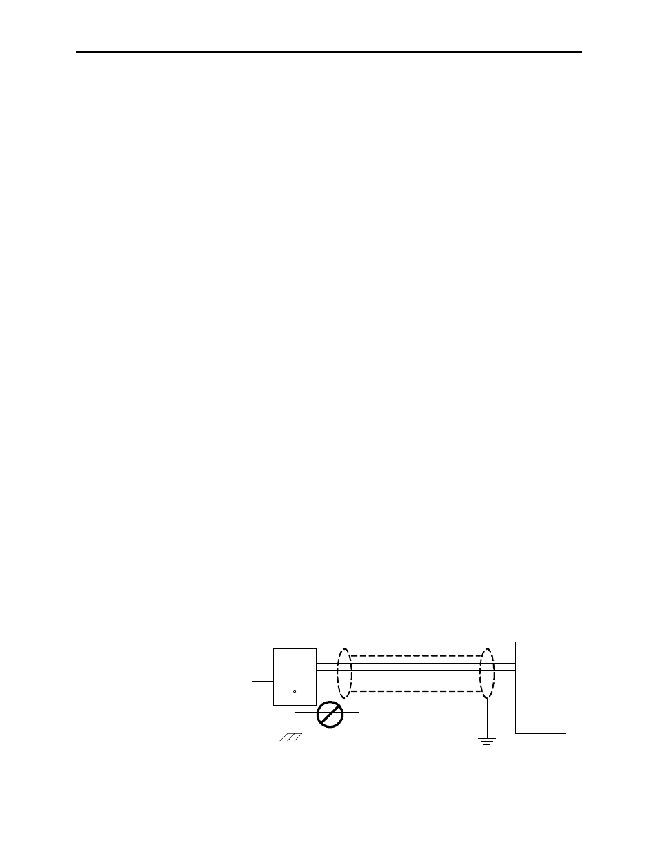
The encoder case must be grounded to the building ground to insure
proper and reliable operation. Most encoders have provision for a
case ground connection through the connector/cable pair if a ground
connection cannot be made through the mounting bracket/machine
ground. DO NOT ground the encoder case through both the
machine and cable wiring. Use low capacitance wires ( ≤ 40pf/ft)
with 100% shield coverage for long cable runs and connect the shield
only at the drive end.
Wrong Shield
Connection
Encoder
Drive
Figure 2.63 – Detail Power Terminal Dimensions
Power and Control Wiring
(cont.)