Topology – Rockwell Automation 7000L PowerFlex 7000 Medium Voltage AC Drive C Frame - Marine User Manual
Page 17
Overview of Drive 1-3
7000 “C” Frame - Marine
7000L-UM302B-EN-P – June 2013
“Plug and play” Power Cage concept
– Central location for easy access to all main power
components
– Common modular design for rectifier / inverter
– Same concept as air-cooled drive for front access, easy
component replacement, and no special tools
– 5-10 minutes to replace main power devices
– No need to remove any cooling lines for device replacement
– Reduced manufacturing time for faster delivery and lower cost
Keyed mechanical interlock
– Interlocked with main disconnect means to prevent unsafe
access to medium voltage section
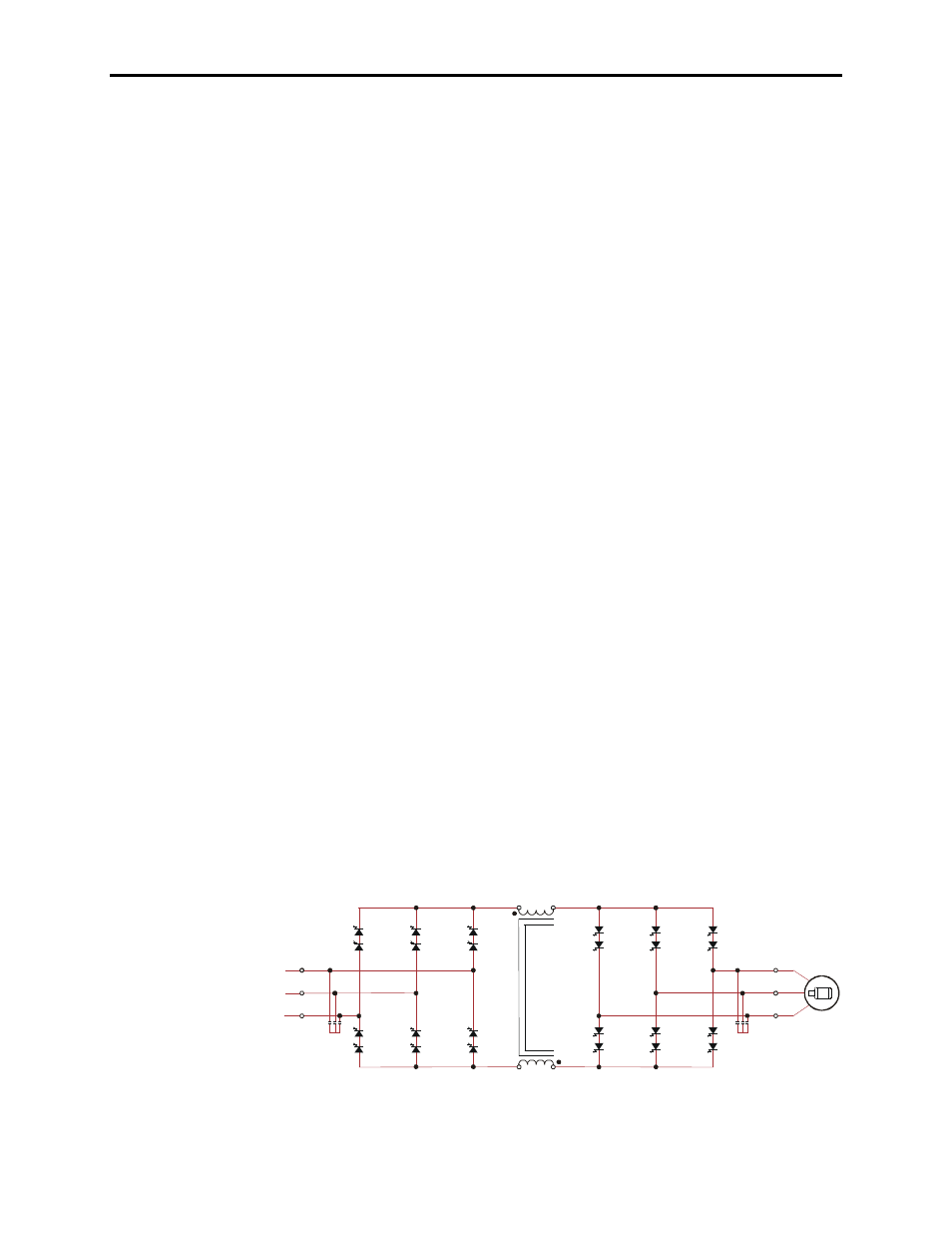
Topology
The PowerFlex 7000L utilizes a Pulse Width Modulated (PWM) –
Current Source Inverter (CSI) for the machine side converter as
shown in Figure 1.1. This topology offers a simple, reliable, cost
effective power structure that is easy to apply to a wide voltage and
power range. The power semiconductor switches used are easy-to-
series for any medium voltage level. Semiconductor fuses are not
required for the power structure due to the current limiting DC link
inductor.
With 6500 volt PIV rated power semiconductor devices, the number
of inverter components is kept to a minimum. For example, only six
inverter switching devices are required at 2400V, 12 at 3300-4160V,
and 18 at 6600V.
The PowerFlex 7000L has the additional benefit of inherent
regenerative braking for applications where the load is overhauling
the motor (i.e. downhill conveyors, etc.), or where high inertia loads
(i.e. fans, etc.) need to be slowed down quickly. Symmetrical Gate
Commutated Thyristors (SGCTs) are used for machine converter
switches. Silicon-controlled rectifiers (SCRs) (for 18 pulse) or
SGCTs (for AFE rectifiers) are used for the line converter switches.
An AFE configuration is shown in Figure 1.1.
2U (X1)
2V (X2)
2W (X3)
SGCTs
LINE C ONVERTER
DC LINK
L+
M+
SGCTs
MACHINE C ONVERTER
U (T1)
V (T2)
W (T3)
L-
M-
Figure 1.1 – AFE Rectifier (4160 Volt)