Cooling system (cont.) – Rockwell Automation 7000L PowerFlex 7000 Medium Voltage AC Drive C Frame - Marine User Manual
Page 244
4-68
Component Definition and Maintenance
7000L-UM302B-EN-P – June 2013
7000 ―C‖ Frame - Marine
Cooling System (cont.)
Cooling Circuit
This circuit is required to cool such devices as Silicon Controlled
Rectifier (SCR), Symmetrical Gate Commutated Thyristor (SGCT),
snubber resistors and sharing resistors. The SCRs and SGCTs are
positioned between two chill blocks in an alternating fashion to
create a horizontal stack. The sharing and snubber resistors on
mounted on a plate with cooling tubes embedded within. As cool
liquid flows through the cooling tubes the entire plate is cooled,
which in turn cools the resistors.
Chill Blocks
The chill blocks are constructed of highly conductive copper
machined parts that are silver soldered together. The parts are
machined to a fine surface finish. The copper chill block provides
good heat transfer from the electrical device to the chillblock. The
coolant system is connected to each chill block with flexible 10-mm
(3/8-in.) hose which fits onto stainless steel hose barbs which are
part of the chill block assembly.
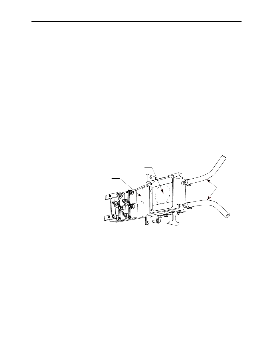
Plate with Cooling Tubes
Chill Block
Coolant Hose
Figure 4.53 – Chill Block Assembly
Coolant Pumps
Two pumps (P1 and P2) are used to move coolant through the
system (Figure 4.54). One of the pumps is used as a backup. The
control logic alternates the primary and secondary pump once every
eight (8) hours. Ensure that the pumps never run dry, as this will
damage the pump seals. Ensure the pumps don‘t cavitate (pumping
air pockets) when filling the system.