Rockwell Automation 7000L PowerFlex 7000 Medium Voltage AC Drive C Frame - Marine User Manual
Page 41
Drive Installation 2-11
7000 “C” Frame - Marine
7000L-UM302B-EN-P – June 2013
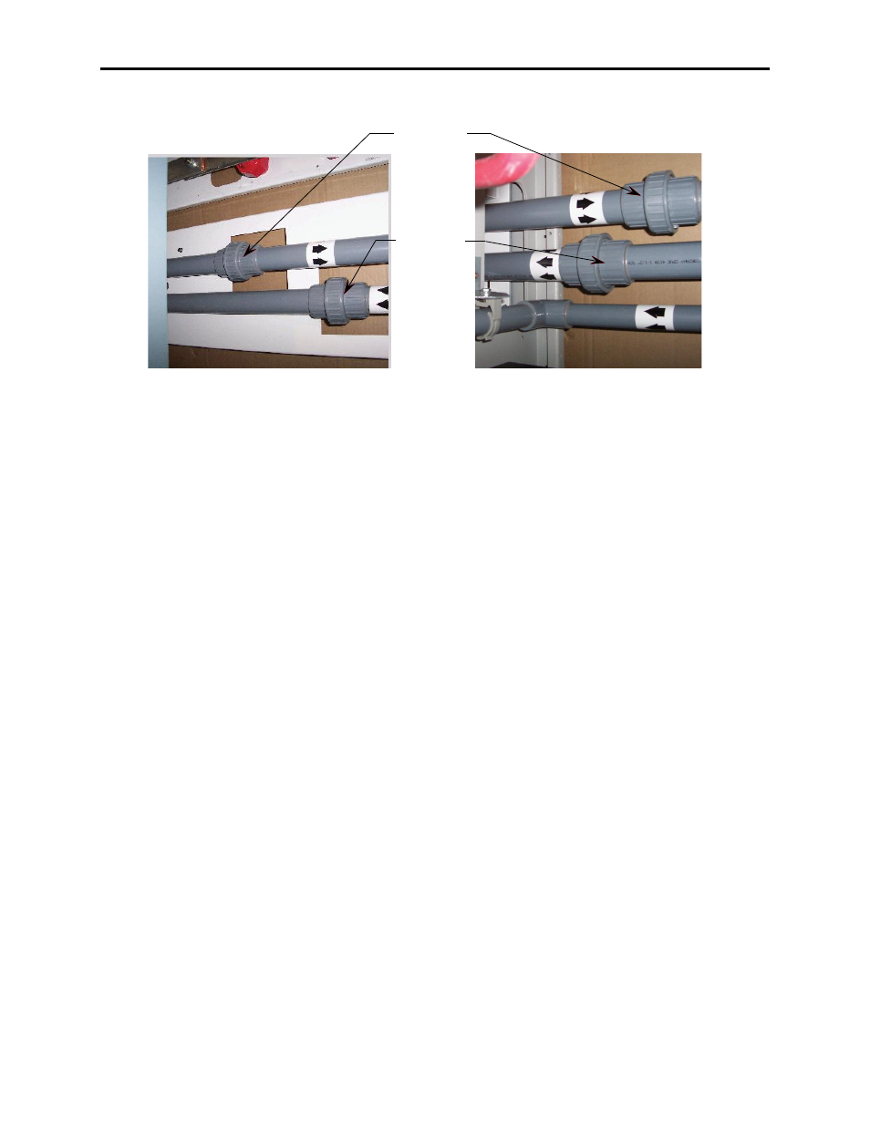
Pipe Splice #1
Pipe Splice #2
Figure 2.7 – Capacitor Cabinet after pipe
splices installed
Figure 2.8 – DC Link Choke Cabinet after
pipe splices installed
Note: Install according to flow direction labels as shown.
Connect Power: M+, L+, M-, L- Power Bus
Locate the four (4) Power Bus pieces of the splice kit in DC Link
Choke cabinet and remove shipping wrapping. See Figure 2.9.
Connect Power Bus M+, L+, M-, L- on the red insulators in the DC
Link Choke cabinet and mating bus pieces in the capacitor cabinet.
Hardware required is pre-attached to bus connections, cabling, and
insulators in the cabinet where the power bus splice kit will attach.
Remove and attach as shown in Figures 2.9 to 2.13.
Torque M10 carriage bolts connecting bus to bus in the capacitor
cabinet to 29 Nm (21 ft-lbs). Torque M12 hardware supplied for
cable to bus stab connections to 50 Nm (37 ft-lbs).
After cable connections have been made, ensure cable connections to
choke stabs are torqued to 50 Nm (37 ft-lbs)
Ensure a minimum of 3” (75mm) clearance exists between Medium
Voltage Bus field connections (including hardware)
and all cabinet sidesheets.