Rockwell Automation 7000L PowerFlex 7000 Medium Voltage AC Drive C Frame - Marine User Manual
Page 215
Component Definition and Maintenance 4-39
7000 ―C‖ Frame - Marine
7000L-UM302B-EN-P – June 2013
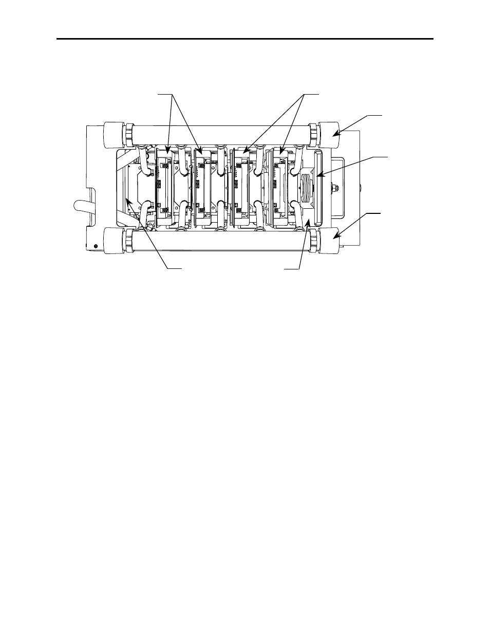
Matched Set 2 SGCTs
Module Housing
Outlet Manifold
Clamp Base
Matched Set 2 SGCTs
Clamp Head
Inlet Manifold
Figure 4.30 – Cooling System
Reconnecting the Coolant System to a PowerCage Module
1. Ensure all power is off and locked-out, including the pumping system.
2. Ensure a blanket or plastic sheet is covering the devices below the
PowerCage being serviced. Face shield and full arm chemical resistant
gloves should be worn at all times when performing this task.
3. Attach both the inlet and outlet manifolds to their bracketry, be sure
to close all the pipe clamps.
4. If necessary, remove the device blocking the left outlet hose and
reconnected it to the lower nipple on the chill block to the extreme
left. Make sure to tighten the hose clamp. Repeat this step for all
outlet hoses and than all inlet hoses.
5. Replace all SGCT/SCR devices and circuit boards as described in
―Replacing the Silicon Controlled Rectifier‖ and ―SGCT
Replacement‖.
6. Check coolant levels to ensure there is still enough coolant in the
system. If coolant must be added, see ―Adding Coolant‖ in the
―Cooling Cabinet Components‖ section.