Removal of lifting angles – Rockwell Automation 7000L PowerFlex 7000 Medium Voltage AC Drive C Frame - Marine User Manual
Page 53
Drive Installation 2-23
7000 “C” Frame - Marine
7000L-UM302B-EN-P – June 2013
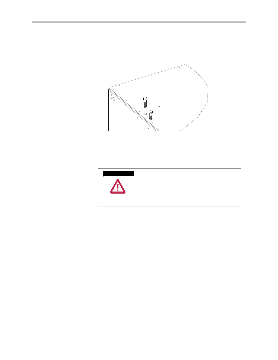
Removal of Lifting Angles
Lifting angles should be removed only when the Drive is in its final
location. The lifting angles are retained with 5/8”-11 hardware. The
5/8” bolts need to be re-installed in their holes in the top of the Drive to
prevent the ingress of foreign matter into the enclosures. See Figure 2.33.
Figure 2.33 – Insert bolts.
A T T E N T I O N
A T T E N T I O N
Refer to the technical drawings and installation
manual for your Drive mounting instructions.
Failure to correctly anchor the cabinet may result
in damage to the equipment or injury to personnel.
Contact the area Rockwell Automation sales
office if you do not have these documents.
An additional set of mounting brackets has been supplied by Rockwell
Automation for securing the drive to the roof for roll and pitch concerns.
The hardware removed for the lifting angles are to be used to secure
these brackets to the drive. An additional mounting drawing, specific for
the order, should be used to understand how to brace the drive to the
vessel structure using these brackets. If this drawing cannot be located,
please contact Rockwell Automation Sales office.