External input/output boards (cont.) – Rockwell Automation 7000L PowerFlex 7000 Medium Voltage AC Drive C Frame - Marine User Manual
Page 286
4-110
Component Definition and Maintenance
7000L-UM302B-EN-P – June 2013
7000 ―C‖ Frame - Marine
The standard drive comes with one XIO board; additional boards (up
to 5) can be daisy chained together from XIO Link B (J5) on the first
board to XIO Link A (J4) on the second board, for a total of 6 XIO
cards. However, at this time the drive only supports the use of
addresses 1 to 3, depending on the drive‘s features and application. U6
on the XIO board displays the board‘s address which is automatically
calculated from the XIO board‘s position in the network.
XIO Link A and B ports are interchangeable but it may make wiring
easier to follow if Link A is used for ―upstream‖, that is, closest to the
ACB, and Link B is used for ―downstream‖ or farthest from the ACB.
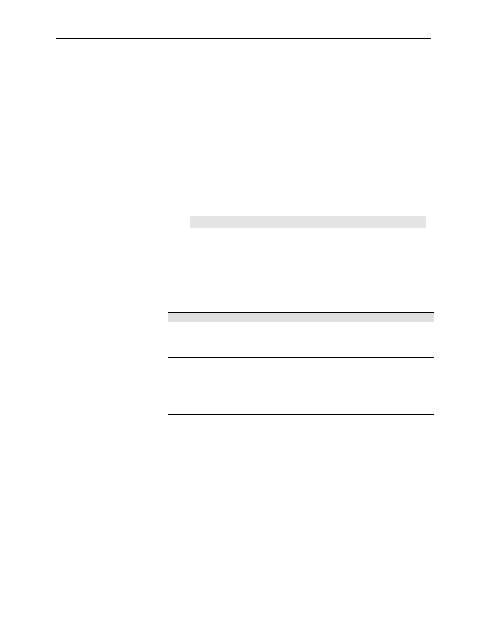
LED D1 and display U6 indicate the status of the board. The
following table illustrates the possible states for D1.
LED Status
Description
Solid Red
Board Failure
Alternate Flashing of Red and
Green
No Communication Available to ACB board
(Normal at Power on, during firmware
download and with unprogrammed drive)
Table 4.F – Status of U6 Display
Display
Description
Explanation
—
No valid address found
– More than 6 XIO cards on network
– XIO cable failure
– XIO card failure
– ACB failure
0
Card in ―Master‖ mode
– Rockwell Use Only
– Remove connection to J3 and recycle power
1 – 6
Valid address
– Normal
Decimal point ON
Indicates network activity
– Normal
Decimal point OFF No activity on the network
– Normal at Power on, during firmware
download and with unprogrammed drive
External Input/Output Boards
(cont.)