Rockwell Automation 7000L PowerFlex 7000 Medium Voltage AC Drive C Frame - Marine User Manual
Page 19
Overview of Drive 1-5
7000 “C” Frame - Marine
7000L-UM302B-EN-P – June 2013
Active Front End (AFE Rectifier)
An active front end (AFE rectifier) suitable for the PowerFlex 7000L
topology is also commonly called a PWM rectifier. This is particularly
attractive since it does not require an isolation transformer to meet
IEEE 519-1992. Most available technologies in today‟s MV market
require a multi-winding transformer to mitigate the unwanted
harmonics by phase shifting the transformer secondary windings.
Depending on the topology, the transformer can have up to 15 sets of
secondary windings. Elimination of the isolation transformer reduces
capital and installation costs, saves on valuable floor space, and
increases overall system efficiency.
The AFE rectifier requires a switching pattern that complies with
similar rules as the inverter. The pattern, used for the example shown
in Figure 1.3, is a 42-pulse selective harmonic elimination (SHE)
pattern, which eliminates the 5
th
, 7th and 11
th
harmonics. The integral
input capacitors are designed to reduce the current harmonics of the
higher order. The filter transfer function technique is used to place the
filter break frequency in a region where no harmonics are present. This
prevents the excitation of system harmonic frequencies. Other factors
that are considered when designing the filter are the input power
factor and the requirement on Total Harmonic Distortion (THD) of
input current and voltage waveforms.
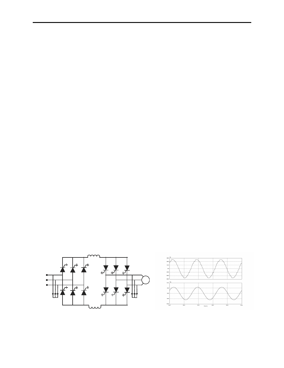
The AFE rectifier is ideal when a distribution transformer is required
to step down the distribution voltage to match the VFD and motor
voltage. The rectifier input current, the rectifier terminal voltage and
the line current and voltage waveforms are shown in Figure 1.3. The
line current THD is approximately 4.5%, while line-to-line voltage
THD is approximately 1.5%. (THD of line voltage is a function of
system impedance.) Input power factor with the AFE rectifier is
equal to or greater than 0.98 for the typical speed and load range
when applied to variable torque loads.
Figure 1.3 – Active rectifier (PWM) and its input current/voltage waveforms
a) Line current
b) Line-to-line voltage at PCC
a)
b)