Rockwell Automation 7000L PowerFlex 7000 Medium Voltage AC Drive C Frame - Marine User Manual
Page 207
Component Definition and Maintenance 4-31
7000 ―C‖ Frame - Marine
7000L-UM302B-EN-P – June 2013
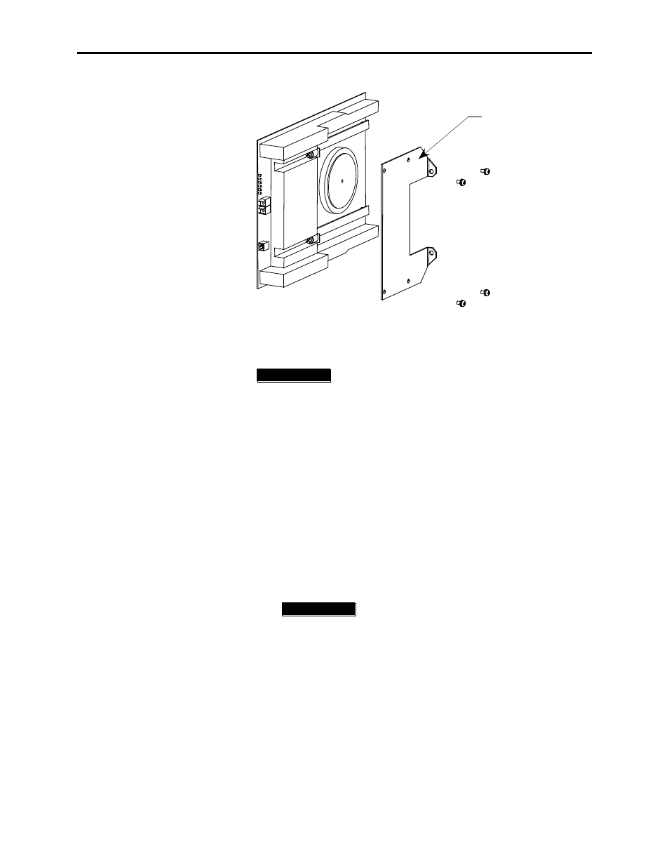
SGCT Brace
Figure 4.22 – Replacing the SGCT – Brace Angle
I M P O R T A N T
I M P O R T A N T
SGCTs come in matched sets in systems with
more than one device per leg. When replacing the
device, it is necessary to replace all devices in the
matched set even if only one has failed.
7. While grounded, remove the SGCT from the anti-static bag it is
supplied in.
8. Assemble the brace angle from the old SGCT to the new SGCT.
9. Apply a thin layer of Electrical Joint Compound (Alcoa EJC No. 2
or approved equivalent) to the contact faces of the new SGCTs
to be installed. The recommended procedure is to apply the
compound to the pole faces using a small brush, and then gently
wipe the pole face with an industrial wipe so that a thin film
remains. Examine the pole face before proceeding to ensure that
no brush bristles remain.
I M P O R T A N T
I M P O R T A N T
Too much joint compound may result in
contamination of other surfaces leading to
system damage.
10. Slide the SGCT into place until the mounting brackets contact the
surface of the chill block. Do not force SGCT when inserting
into place. Make sure it slides in with little resistance. Use a
Phillips screwdriver to tighten the captive screws to the cathode
side of the chill block.
11. Readjust the clamping load as described in ―Checking Clamping
Pressure‖.
12. Connect the control power cable and fiber optic cables (ensure
the bend radius is not exceeded).