Digital filter – Rockwell Automation 1756-XXXX ControlLogix Analog I/O Modules User Manual
Page 99
Publication 1756-UM009C-EN-P - December 2010
99
Sourcing Current Loop Input Module (1756-IF6CIS) and Isolated Analog Voltage/Current Input Module (1756-IF6I) Chapter 5
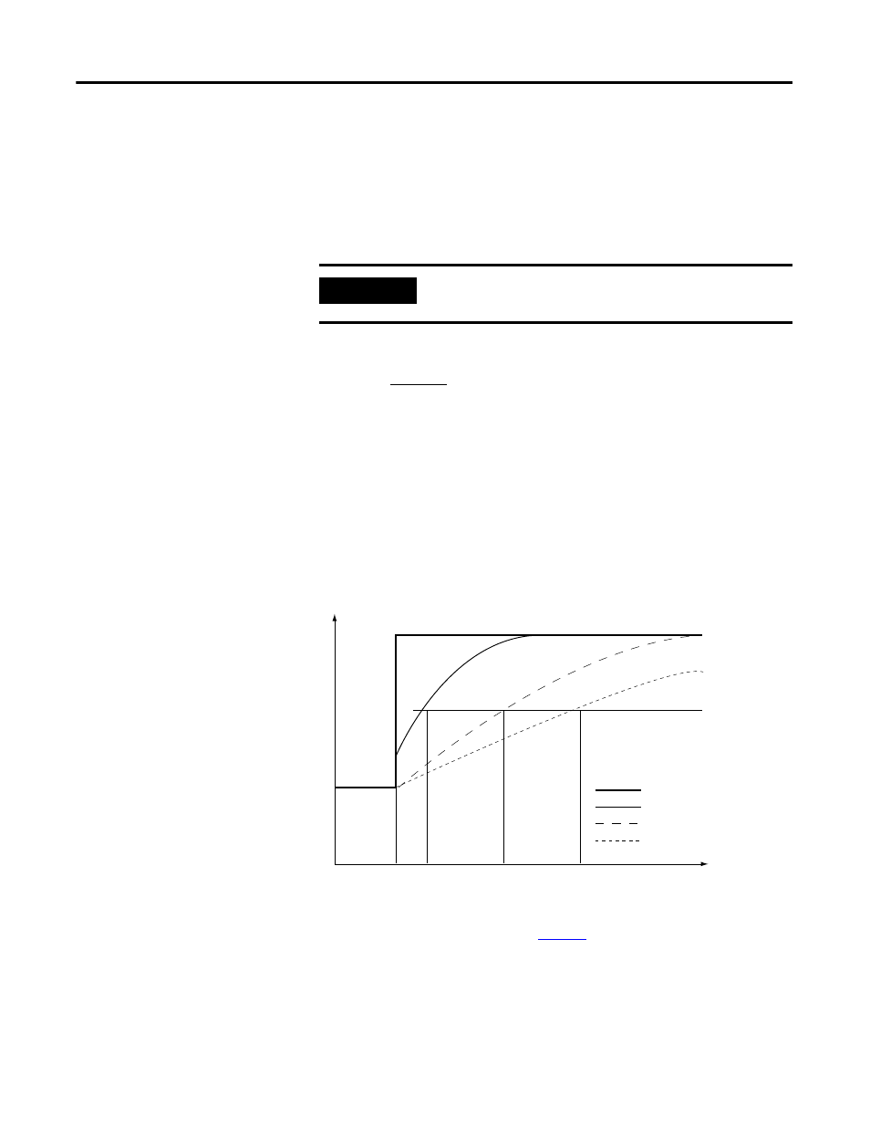
Digital Filter
The digital filter smooths input data noise transients on
each input channel.
This value specifies the time constant for a digital, first-order lag filter on the
input. It is specified in units of milliseconds. A value of 0 (zero) disables
the filter.
The digital filter equation is a classic, first order lag equation.
As shown in the illustration, by using a step input change to illustrate the filter
response, you see that 63.2% of the total response is reached when the digital
filter time constant elapses. Each additional time constant achieves 63.2% of
the remaining response.
To see how to set a digital filter, see
IMPORTANT
The digital filter is available only in applications that use
floating point mode.
Yn = Yn-1 +
(X
n
– Y
n
-1)
[
Δ
t]
Δ
t + TA
Yn = Present output, filtered peak voltage (PV)
Yn-1 = Previous output, filtered PV
Δ
t = Module channel update time (seconds)
TA = Digital filter time constant (seconds)
Xn = Present input, unfiltered PV
0
0.01
0.5
0.99
Time in Seconds
16723
100%
63%
0
Amplitude
Unfiltered input
TA = 0.01 second
TA = 0.5 second
TA = 0.99 second