Rockwell Automation 1756-XXXX ControlLogix Analog I/O Modules User Manual
Page 295
Publication 1756-UM009C-EN-P - December 2010
295
Analog I/O Module Specifications Appendix A
1
2
3
4
5
6
7
8
9
10
11
12
13
14
15
16
17
18
19
20
21
22
23
24
25
26
27
28
29
30
31
32
33
34
35
36
Shield
Ground
Jumper
Wires
i
i
A
2-wire
Transmitter
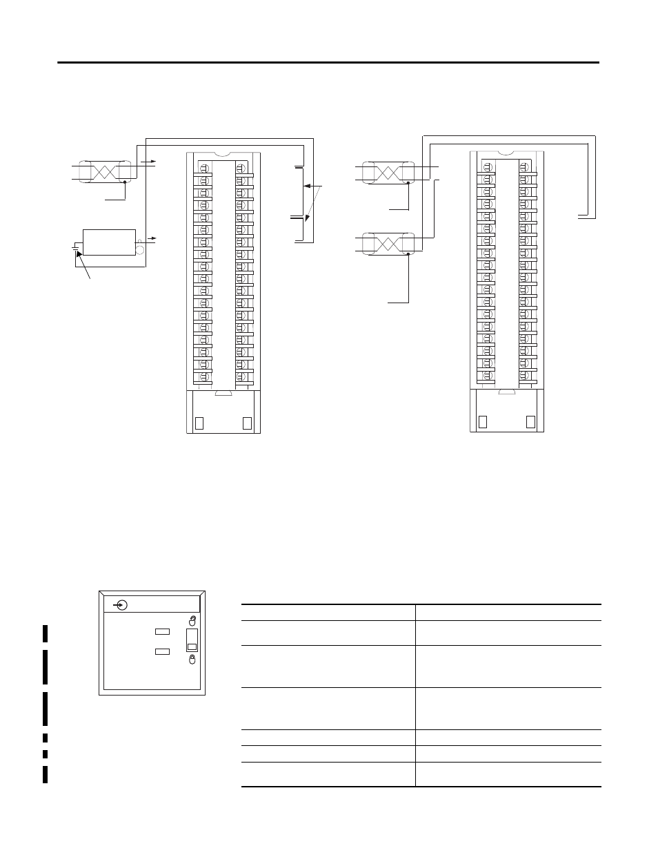
1756-IF16 Single-ended Current
IN-0
IN-1
IN-2
IN-3
IN-7
RTN
IN-4
IN-5
IN-6
IN-15
IN-8
IN-9
IN-10
IN-11
RTN
IN-12
IN-13
IN-14
i RTN-0
i RTN-1
i RTN-2
i RTN-3
i RTN-7
RTN
i RTN-4
i RTN-5
i RTN-6
i RTN-15
i RTN-8
i RTN-9
i RTN-10
i RTN-11
RTN
i RTN-12
i RTN-13
i RTN-14
1
2
3
4
5
6
7
8
9
10
11
12
13
14
15
16
17
18
19
20
21
22
23
24
25
26
27
28
29
30
31
32
33
34
35
36
+
–
+
–
Shield
Ground
1756-IF16 Single-ended Voltage
IN-0
IN-1
IN-2
IN-3
IN-7
RTN
IN-4
IN-5
IN-6
IN-15
IN-8
IN-9
IN-10
IN-11
RTN
IN-12
IN-13
IN-14
i RTN-0
i RTN-1
i RTN-2
i RTN-3
i RTN-7
RTN
i RTN-4
i RTN-5
i RTN-6
i RTN-15
i RTN-8
i RTN-9
i RTN-10
i RTN-11
RTN
i RTN-12
i RTN-13
i RTN-14
Shield
Ground
· All terminals marked RTN are connected internally.
· For current applications, all terminals marked i RTN must be
wired to terminals marked RTN.
· A 249
Ω
current loop resistor is located between IN-x and
iRTN-x terminals.
· Place additional loop devices (such as strip chart recorders) at
the A location in the current loop.
· Do not connect more than two wires to any single terminal.
· All terminals marked RTN are connected internally.
· Terminals marked i RTN are not used for single-ended voltage
wiring.
· Do not connect more than two wires to any single terminal.
User-provided
Loop Power
Technical Specifications - 1756-IF16
Attribute
1756-IF16
Inputs
16 single ended, 8 differential or
4 differential (high-speed)
Input range
±10.25V
0…10.25V
0…5.125V
0…20.5 mA
Resolution
±10.25V (15 bits + sign bit)
0…10.25V (16 bits)
0…5.1 (16 bits)
0…20.5 mA (16 bits)
Current draw @ 5.1V
150 mA
Current draw @ 24V
65 mA
Power dissipation, max
Voltage:2.3 W
Current:3.9 W
ANALOG INPUT
CAL
OK
HART