Fault reporting in integer mode – Rockwell Automation 1756-XXXX ControlLogix Analog I/O Modules User Manual
Page 145
Publication 1756-UM009C-EN-P - December 2010
145
Temperature-measuring Analog Modules (1756-IR6I, 1756-IT6I, and 1756-IT6I2) Chapter 6
Fault Reporting in
Integer Mode
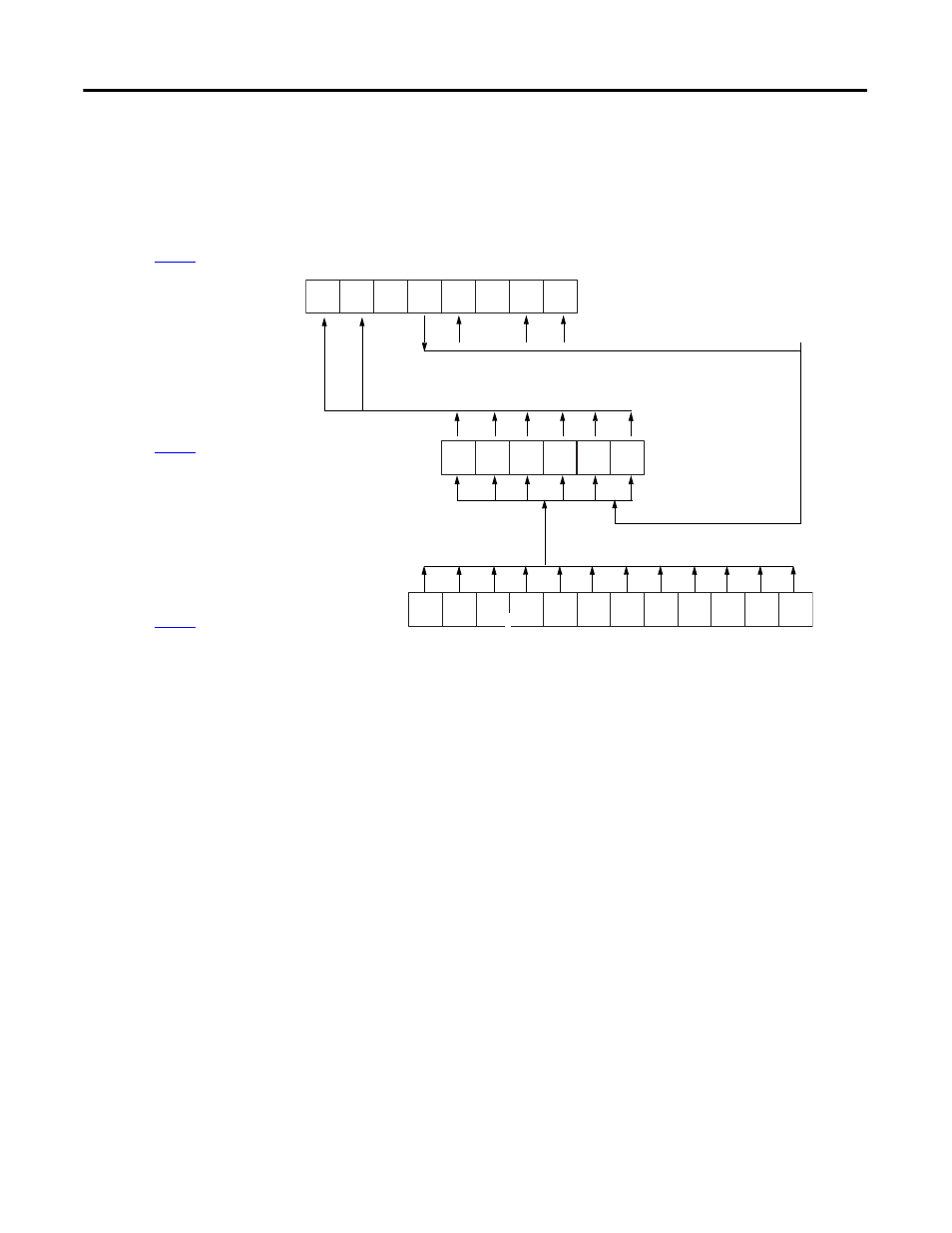
The illustration offers an overview of the fault reporting process in integer
mode.
15
14
13
12
11
10
9
8
5
4
3
2
1
0
5
4
9
8
7
6
15 = AnalogGroupFault
14 = InGroupFault
12 = Calibrating
11 = Cal Fault
9 and 8 = CJUnderOver
13 and 10 are not used
by 1756-IR6I or IT6I
5 = Ch5Fault
4 = Ch4Fault
3 = Ch3Fault
2 = Ch2Fault
1 = Ch1Fault
0 = Ch0Fault
15 = Ch0Underrange
14 = Ch0Overrange
13 = Ch1Underrange
12 = Ch1Overrange
11 = Ch2Underrange
10 = Ch2Overrange
41349
15
14
13
12
11
10
9 = Ch3Underrange
8 = Ch3Overrange
7 = Ch4Underrange
6 = Ch4Overrange
5 = Ch5Underrange
4 = Ch5Overrange
Underrange and overrange conditions set the corresponding
Channel Fault word bit for that channel.
When the module is
calibrating, all bits
in the Channel Fault
word are set.
Any bit in the Channel Fault word, also sets the Analog Group
Fault and Input Group Fault in the Module Fault word
A calibrating fault
sets bit 11 in the
Module Fault word
Cold Junction temperature
underrange and overrange
conditions set bits 9 and 8
for 1756-IT6I only
Module Fault Word
(described on
)
Channel Fault Word
(described on
)
Channel Status Words
(described on
)