Rockwell Automation 1756-XXXX ControlLogix Analog I/O Modules User Manual
Page 160
160
Publication 1756-UM009C-EN-P - December 2010
Chapter 7 Non-isolated Analog Output Modules (1756-OF4 and 1756-OF8)
1756-OF4 and 1756-OF8
Fault Reporting in
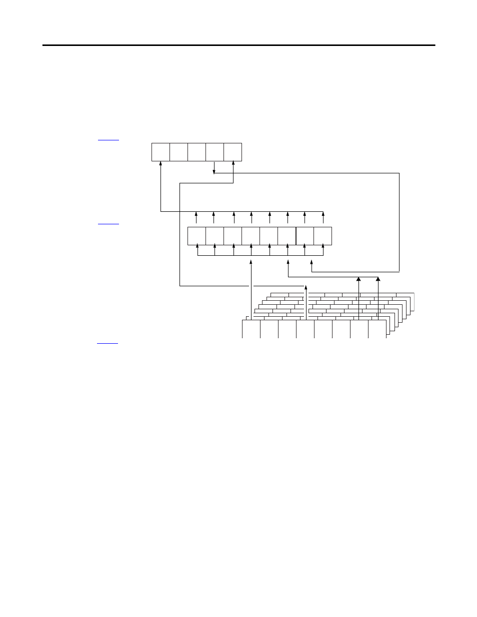
Floating Point Mode
The illustration offers an overview of the fault reporting process in
floating point mode.
Module Fault Word
)
Channel Fault Word
)
Channel Status Words
(one for each channel–
)
15
14
13
12
11
5
4
3
2
1
0
5
4
3
2
1
0
7
6
15 = AnalogGroupFault
12 = Calibrating
11 = Cal Fault
14 and 13 are not used by
the 1756-OF4 or 1756-OF8
7 = Ch7Fault
6 = Ch6Fault
5 = Ch5Fault
4 = Ch4Fault
3 = Ch3Fault
2 = Ch2Fault
1 = Ch1Fault
0 = Ch0Fault
7 = ChxOpenWire
5 = ChxNotANumber
4 = ChxCalFault
3 = ChxInHold
2 = ChxRampAlarm
1 = ChxLLimitAlarm
0 = ChxHLimitAlarm
Not a Number, Output in Hold, and Ramp
Alarm conditions do not set additional
bits. You must monitor them here.
Number six is not used by
1756-OF4 or 1756-OF8
If set, any bit in the Channel Fault word, also sets
the Analog Group Fault in the Module Fault word.
A channel
calibration fault
sets the
calibration fault
in the Module
Fault word.
When the module is calibrating, all
bits in the Channel Fault word are set.
IMPORTANT:1756-OF4 uses four Channel Status Words. 1756-OF8
uses eight Channel Status words. This graphic shows eight words.
7
6
41519