Wire the 1756-of4 module – Rockwell Automation 1756-XXXX ControlLogix Analog I/O Modules User Manual
Page 157
Publication 1756-UM009C-EN-P - December 2010
157
Non-isolated Analog Output Modules (1756-OF4 and 1756-OF8) Chapter 7
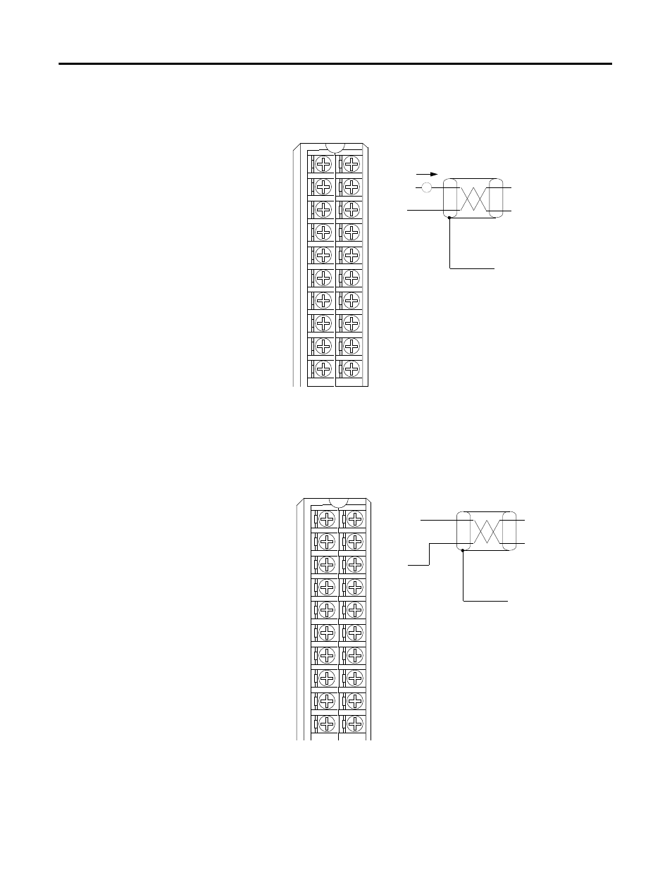
Wire the 1756-OF4 Module
The illustration shows wiring examples for the 1756-OF4 module.
1756-OF4 Current wiring example
1756-OF4 Voltage wiring example
VOUT-2
IOUT-2
RTN
VOUT-3
IOUT-3
VOUT-0
IOUT-0
RTN
VOUT-1
IOUT-1
1
2
3
4
5
6
7
8
9
10
11
12
13
14
15
16
17
18
19
20
i
Not used
Not used
RTN
Not used
Not used
RTN
Not used
Not used
A
NOTES:
1. Place additional loop devices (that is, strip chart recorders, and so forth) at the A location
noted above.
2. Do not connect more than two wires to any single terminal.
3. All terminals marked RTN are connected internally.
Not used
Not used
Current
output
load
Shield ground
40916-M
Not used
Not used
RTN
Not used
Not used
Not used
Not used
RTN
Not used
Not used
VOUT-O
IOUT-O
RTN
VOUT-1
IOUT-1
VOUT-2
IOUT-2
RTN
VOUT-3
IOUT-3
VOUT-2
IOUT-2
RTN
VOUT-3
IOUT-3
VOUT-0
IOUT-0
RTN
VOUT-1
IOUT-1
1
2
3
4
5
6
7
8
9
10
11
12
13
14
15
16
17
18
19
20
+
–
Not used
Not used
RTN
Not used
Not used
RTN
Not used
Not used
NOTES:
1. Do not connect more than two wires to any single terminal.
2. All terminals marked RTN are connected internally.
Not used
Not used
Shield ground
40912-M
Not used
Not used
Not used
Not used
Not used
Not used
Not used
Not used
RTN
RTN
RTN
RTN
VOUT-O
IOUT-O
VOUT-1
IOUT-1
VOUT-2
IOUT-2
VOUT-3
IOUT-3