Drive different loads with the 1756-of6ci, Field-side circuit diagrams – Rockwell Automation 1756-XXXX ControlLogix Analog I/O Modules User Manual
Page 174
174
Publication 1756-UM009C-EN-P - December 2010
Chapter 8 Isolated Analog Output Modules (1756-OF6CI and 1756-OF6VI)
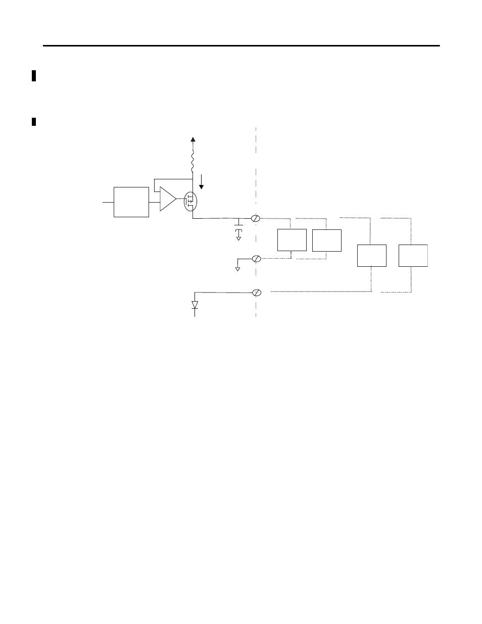
Field-side Circuit Diagrams
The diagram shows field-side circuitry for the 1756-OF6CI module.
1756-OF6CI Output Circuit
Drive Different Loads
with the 1756-OF6CI
The 1756-OF6CI module’s output stage provides a constant current that flows
through its internal electronics and out through the external output load. Since
the output current is constant, the only variable in the current loop is the
voltage across the output electronics and the voltage across the load. For a
given termination option, the sum of the individual voltage drops around the
loop components must add up to the total available voltage (13V for
OUT-x/RTN-x termination and 26V for OUT-x / ALT-x).
As seen in the above diagram, a larger external output load will drop a larger
portion of the available loop voltage, allowing the module to drop less volts
across its internal output electronics. This lower drop allows the power
dissipation in the module to be lower, minimizing the thermal affect to
adjacent modules in the same chassis.
43503
–
250
Ω
5V @ 20mA
+13V
+
Iout = 0-21mA
D/A Convertor
& Current
Amplifier
-13V
500
Ω
10V @ 20mA
750
Ω
15V @ 20mA
1000
Ω
20V @ 20mA
Field
Side
System
Side
50
Ω
Vdrop 1.0V @ 20mA
OUT-0
0.22
μ
F
RTN-0
ALT-0