Rockwell Automation 1756-XXXX ControlLogix Analog I/O Modules User Manual
Page 336
336
Publication 1756-UM009C-EN-P - December 2010
Appendix B Analog I/O Tag Definitions
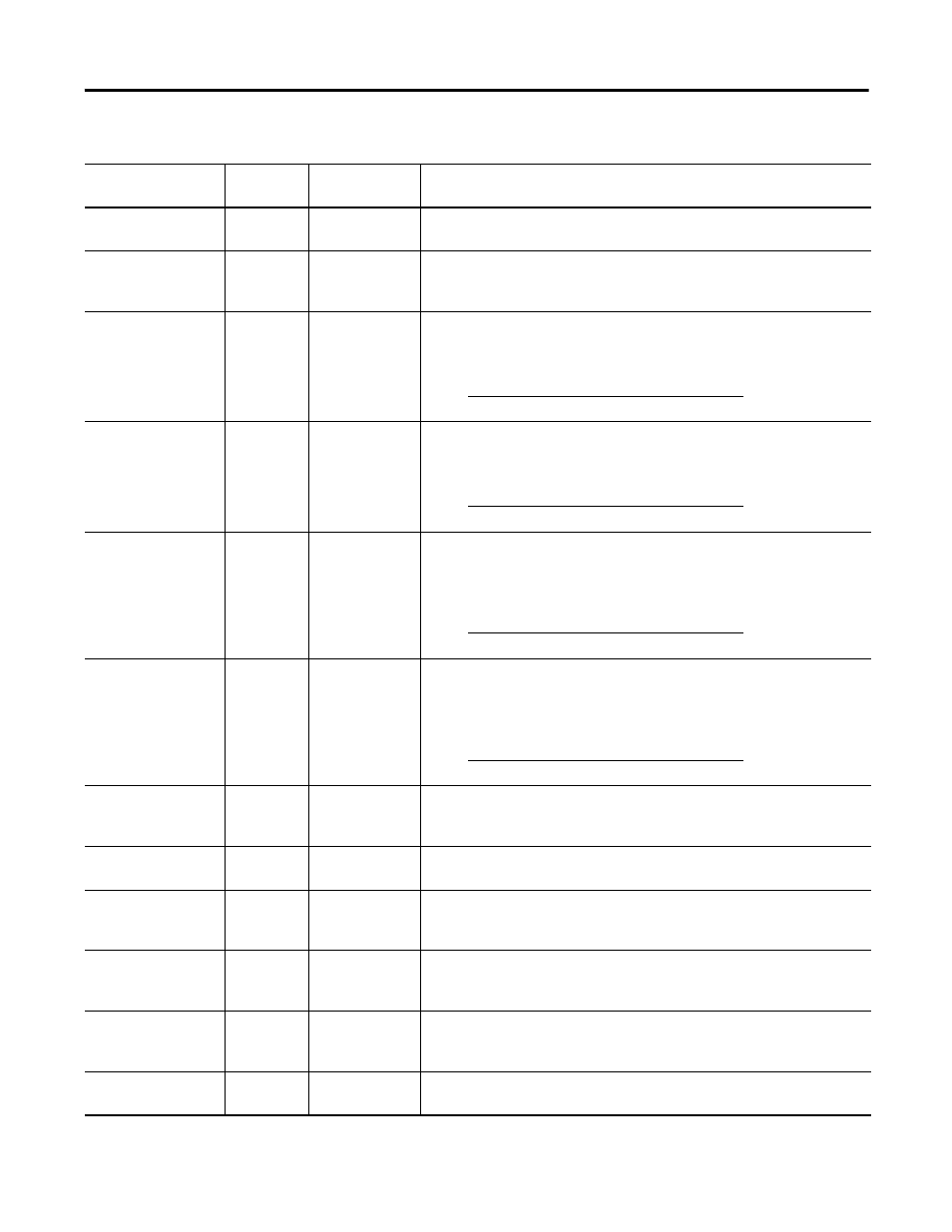
Ch0ConfigTenOhm
Offset
INT
1756-IR6I
A value from -100…100 that represents -1.00…1.00
Ω
and is an offset used
when linearizing a 10
Ω
copper sensor type’s input.
Ch0ConfigRate
AlarmLimit
INT
All inputs
The trigger point for the rate alarm status bit that sets if the input signal
changes at a rate faster than the configured rate alarm. Configured in percent
full scale per second.
Ch0ConfigLow
Signal
REAL
All
One of four points used in scaling. The low signal is in terms of the inputs
signal units and corresponds to the low engineering term when scaled. The
scaling equation is shown below.
Ch0ConfigHigh
Signal
REAL
All
One of four points used in scaling. The high signal is in terms of the inputs
signal units and corresponds to the high engineering term when scaled. The
scaling equation is shown below.
Ch0ConfigLow
Engineering
REAL
All
One of four points used in scaling. The low engineering helps determine the
engineering units the signal values scale into. The low engineering term
corresponds to the low signal value. The scaling equation used is
shown below.
C0ConfigHigh
Engineering
REAL
All
One of four points used in scaling. The high engineering helps determine the
engineering units the signal values scale into. The high engineering term
corresponds to the high signal value. The scaling equation used is shown
below.
Ch0ConfigLAlarm
Limit
REAL
All inputs
The low alarm trigger point. Causes the Ch0LAlarm to trigger when the input
signal moves beneath the configured trigger point. In terms of
engineering units.
Ch0ConfigHAlarm
Limit
REAL
All inputs
The high alarm trigger point. Causes the Ch0HAlarm to trigger when the input
signal moves above the configured trigger point. In terms of engineering units.
Ch0ConfigLLAlarm
Limit
REAL
All inputs
The low low alarm trigger point. Causes the Ch0LLAlarm to trigger when the
input signal moves beneath the configured trigger point. In terms of
engineering units.
Ch0ConfigHH
AlarmLimit
REAL
All inputs
The high high alarm trigger point. Causes the Ch0HHAlarm to trigger when the
input signal moves above the configured trigger point. In terms of
engineering units.
Ch0ConfigAlarm
Deadband
REAL
All inputs
Forms a deadband around the process alarms that causes the corresponding
process alarm status bit to remain set until the input moves beyond the trigger
point by greater than the amount of the alarm deadband.
Ch0ConfigCalBias
REAL
All inputs
A user-defined offset added directly into the data, Ch0Data. used to
compensate for inherent sensor offset.
Floating Point Configuration Tags
Tag Name
Data Type
Applicable
Modules
Definition
Data =
+ LowEngineering
(Signal - Low Signal) x (High Engineering - Low Engineering)
(High Signal - Low Signal)
Data =
+ LowEngineering
(Signal - Low Signal) x (High Engineering - Low Engineering)
(High Signal - Low Signal)
Data =
+ LowEngineering
(Signal - Low Signal) x (High Engineering - Low Engineering)
(High Signal - Low Signal)
Data =
+ LowEngineering
(Signal - Low Signal) x (High Engineering - Low Engineering)
(High Signal - Low Signal)