Process alarms – Rockwell Automation 1756-XXXX ControlLogix Analog I/O Modules User Manual
Page 100
100
Publication 1756-UM009C-EN-P - December 2010
Chapter 5 Sourcing Current Loop Input Module (1756-IF6CIS) and Isolated Analog Voltage/Current Input Module (1756-IF6I)
Process Alarms
Process alarms alert you when the module has exceeded configured high or
low limits for
each channel. You can latch process alarms. These are set at
four, user-configurable, alarm trigger points.
• High high
• High
• Low
• Low low
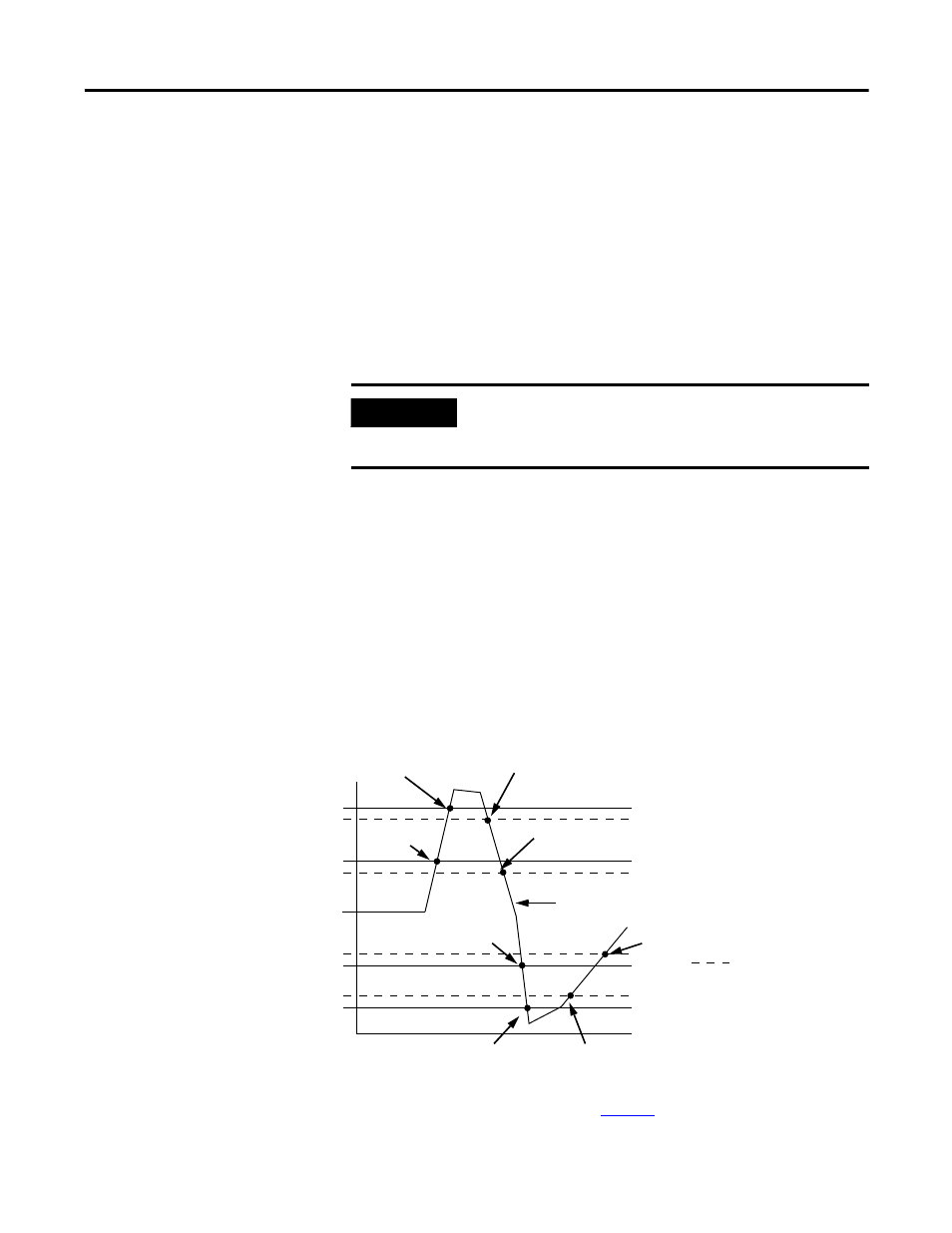
Alarm Deadband
You may configure an alarm deadband to work with these alarms. The
deadband allows the process alarm status bit to remain set, despite the alarm
condition disappearing, as long as the input data remains within the deadband
of the process alarm.
The illustration shows input data that sets each of the four alarms at some
point during module operation. In this example, latching is disabled; therefore,
each alarm turns Off when the condition that caused it to set ceases to exist.
To see how to set process alarms, see
IMPORTANT
Process alarms are available only in applications that use
floating point mode. The values for each limit are entered in
scaled engineering units.
43153
High high
Low low
Low
High
Alarm deadbands
High high alarm turns Off
High alarm remains On
High high alarm turns On
High alarm remains On
Normal input range
Low low alarm turns Off
Low alarm remains On
High alarm turns Off
Low alarm turns On
Low alarm remains On
Low alarm turns Off
Low alarm turns ON
High alarm
turns On