Wire the modules, For a – Rockwell Automation 1756-XXXX ControlLogix Analog I/O Modules User Manual
Page 138
138
Publication 1756-UM009C-EN-P - December 2010
Chapter 6
Temperature-measuring Analog Modules (1756-IR6I, 1756-IT6I, and 1756-IT6I2)
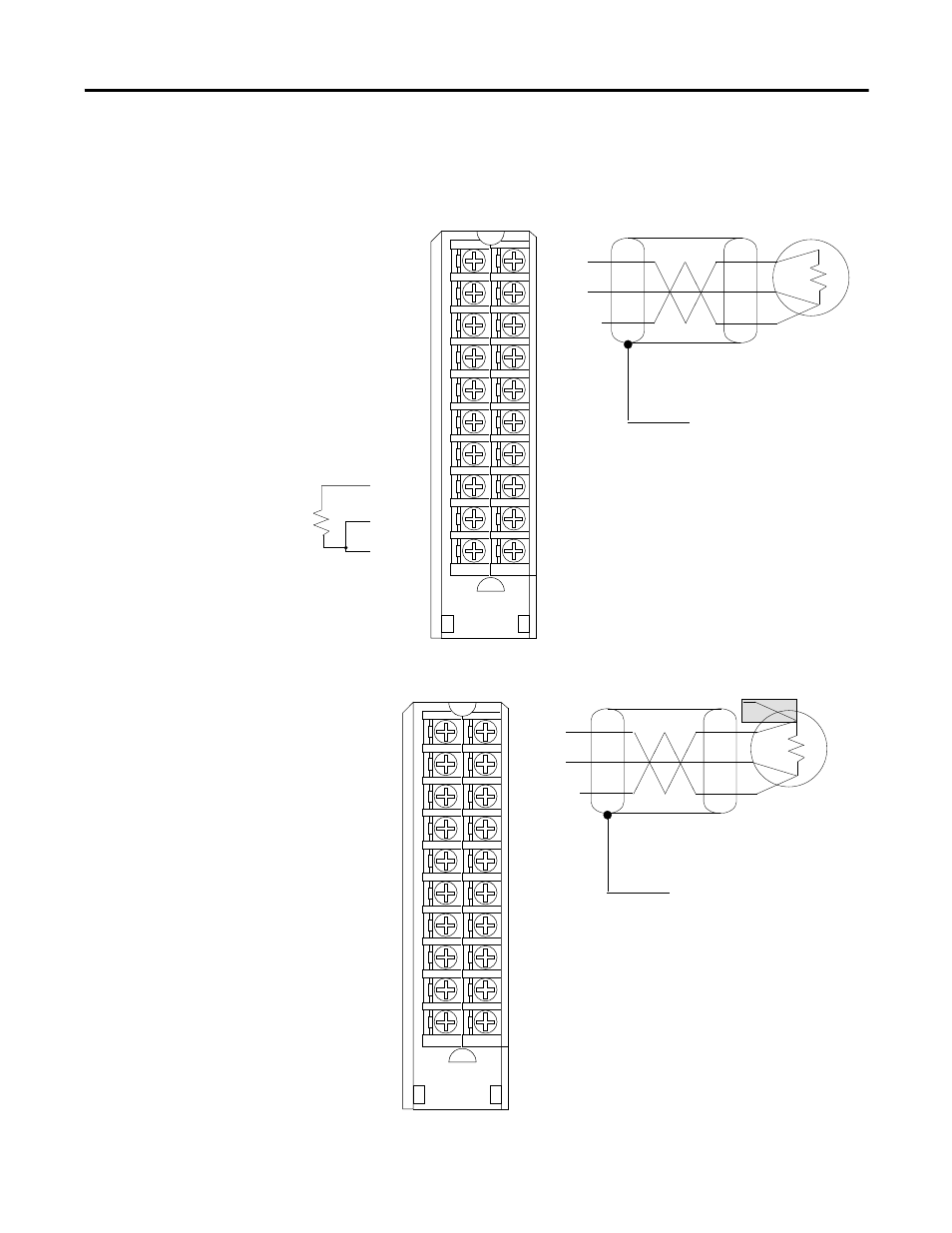
Wire the Modules
The illustrations show wiring examples for the 1756-IR6I, 1756-IT6I, and
1756-IT6I2 modules.
1756-IR6I 3-Wire RTD wiring example
1756-IR6I 4-Wire RTD wiring example
20972-M
Shield Ground
IN-0/A
IN-0/B
RTN-0/C
IN-2/A
IN-2/B
RTN-2/C
Not used
IN-4/A
IN-4/B
RTN-4/C
IN-1/A
IN-1/B
RTN-1/C
IN-3/A
IN-3/B
RTN-3/C
Not used
IN-5/A
IN-5/B
RTN-5/C
3-Wire RTD
1
2
3
4
5
6
7
8
9
10
11
12
13
14
15
16
17
18
19
20
IMPORTANT: For two-wire resistor
applications including
calibration, make sure
IN-x/B and RTN-x/C
are shorted together
as shown.
IN-1/A
IN-0/A
IN-1/B
RTN-1/C
IN-3/A
IN-3/B
RTN-3/C
Not used
IN-5/A
IN-5/B
RTN-5/C
IN-0/B
RTN-0/C
IN-2/A
IN-2/B
RTN-2/C
Not used
IN-4/A
IN-4/B
RTN-4/C
Shield Ground
3-Wire RTD
NOTES:
1. Do not connect more than two wires to
any single terminal.
20973-M
Shield Ground
4-Wire RTD
1
2
3
4
5
6
7
8
9
10
11
12
13
14
15
16
17
18
19
20
IN-0/A
IN-0/B
RTN-0/C
IN-2/A
IN-2/B
RTN-2/C
Not used
IN-4/A
IN-4/B
RTN-4/C
IN-1/A
IN-1/B
RTN-1/C
IN-3/A
IN-3/B
RTN-3/C
Not used
IN-5/A
IN-5/B
RTN-5/C
IN-1/A
IN-1/B
RTN-1/C
IN-3/A
IN-3/B
RTN-3/C
Not used
IN-5/A
IN-5/B
RTN-5/C
IN-0/A
IN-0/B
RTN-0/C
IN-2/A
IN-2/B
RTN-2/C
Not used
IN-4/A
IN-4/B
RTN-4/C
IN-4/A
IN-4/B
4-Wire RTD
Shield Ground
NOTES:
1. Do not connect more than two wires to
any single terminal.
2. Wiring is exactly the same as the
3-Wire RTD with one wire left open.