Rockwell Automation 1756-XXXX ControlLogix Analog I/O Modules User Manual
Page 110
110
Publication 1756-UM009C-EN-P - December 2010
Chapter 5 Sourcing Current Loop Input Module (1756-IF6CIS) and Isolated Analog Voltage/Current Input Module (1756-IF6I)
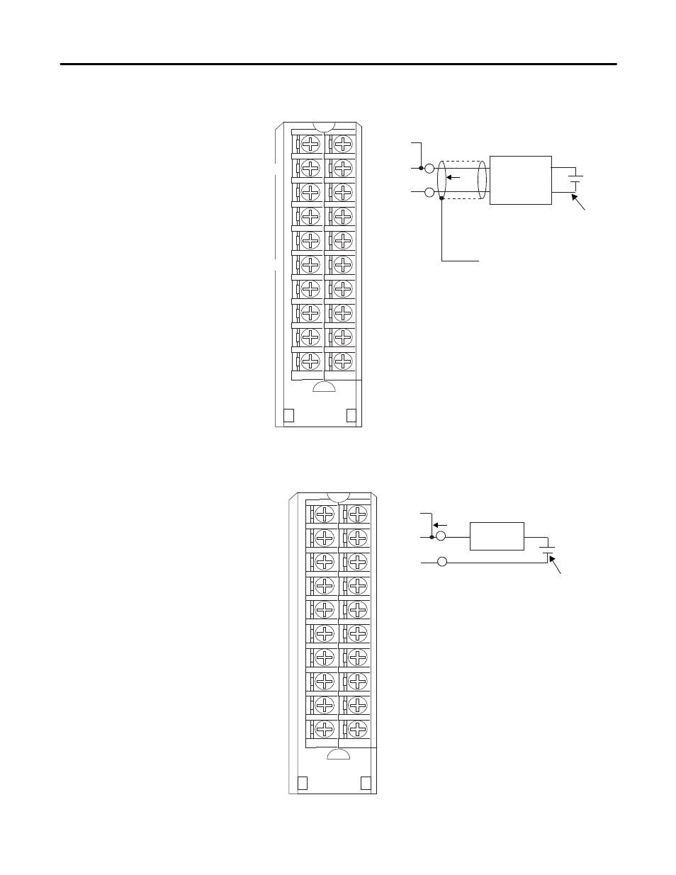
1756-IF6I Current Wiring Example with a Four-Wire Transmitter
1756-IF6I Current Wiring Example with a Two-Wire Transmitter
4-Wire
Transmitter
Shield Ground
+
–
IN-0/V
IN-0/I
RET-0
IN-2/V
IN-2/I
RET-2
Not used
IN-4/V
IN-4/I
RET-4
IN-1/V
IN-1/I
RET-1
IN-3/V
IN-3/I
RET-3
Not used
IN-5/V
IN-5/I
RET-5
1
2
3
4
5
6
7
8
9
10
11
12
13
14
15
16
17
18
19
20
40199-M
i
+
-
A
A
IN-V and IN-I must be wired together.
4-Wire
Transmitter
Shield Ground
40199
IN-I/V
IN-1/I
RET-1
IN-3/V
IN-3/I
RET-3
Not Used
IN-5/V
IN-5/I
RET-5
IN-0/V
IN-0/I
RET-0
IN-2/V
IN-2/I
RET-2
Not Used
IN-4/V
IN-4/I
RET-4
i
NOTES:
1. Do not connect more than two wires to
any single terminal.
2. Place additional loop devices (that is,
strip recorders) at either ’A’ location.
Device
Supply
1
2
3
4
5
6
7
8
9
10
11
12
13
14
15
16
17
18
19
20
IN-1/V
IN-1/I
RET-1
IN-3/V
IN-3/I
RET-3
Not used
IN-5/V
IN-5/I
RET-5
IN-0/V
IN-0/I
RET-0
IN-2/V
IN-2/I
RET-2
Not used
IN-4/V
IN-4/I
RET-4
2-Wire
Transmitter
(+)
(–)
40893-M
i
+
-
A
A
IN-V and IN-I must be wired together.
40893
i
2-Wire
Transmitter
IN-1/V
IN-1/I
RET-1
IN-3/V
IN-3/I
RET-3
Not Used
IN-5/V
IN-5/I
RET-5
IN-0/V
IN-0/I
RET-0
IN-2/V
IN-2/I
RET-2
Not Used
IN-4/V
IN-4/I
RET-4
NOTES:
1. Do not connect more than two wires to
any single terminal.
2. Place additional loop devices (that is,
strip recorders) at either ’A’ location.
User-provided
Loop Power