Rockwell Automation 1756-XXXX ControlLogix Analog I/O Modules User Manual
Page 87
Publication 1756-UM009C-EN-P - December 2010
87
Non-isolated Analog Voltage/Current Input Modules (1756-IF16, 1756-IF8) Chapter 4
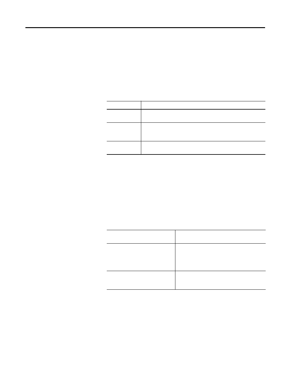
1756-IF8 Module Fault Word Bits – Floating Point Mode
Bits in this word provide the highest level of fault detection. A non-zero
condition in this word reveals that a fault exists on the module. You can
examine further down to isolate the fault.
The table lists tags that can be examined in ladder logic to indicate when a fault
has occurred:
1756-IF8 Channel Fault Word Bits – Floating Point Mode
During normal module operation, bits in the Channel Fault word are set if any
of the respective channels has an Under or Overrange condition. Checking this
word for a non-zero value is a quick way to check for Under or Overrange
conditions on the module.
The table lists the conditions that set
all Channel Fault word bits:
Your logic can monitor the Channel Fault Word bit for a particular input to
determine the state of that point.
Tag
Description
Analog Group
Fault
This bit is set when any bits in the Channel Fault word are set. Its tag
name is AnalogGroupFault.
Calibrating
This bit is set when any channel is being calibrated. When this bit is
set, all bits in the Channel Fault word are set. Its tag name is
Calibrating.
Calibration Fault
This bit is set when any of the individual Channel Calibration Fault bits
are set. Its tag name is CalibrationFault.
This condition sets all Channel
Fault word bits
And causes the module to display the
following in the Channel Fault word bits
A channel is being calibrated
• ‘00FF’ for single-ended wiring applications
• ‘000F’ for differential wiring applications
• ‘0003’ for high speed differential wiring
applications
A communication fault occurred
between the module and its
owner-controller
‘FFFF’ for all bits, regardless of the application