1756-if8 fault reporting in integer mode – Rockwell Automation 1756-XXXX ControlLogix Analog I/O Modules User Manual
Page 89
Publication 1756-UM009C-EN-P - December 2010
89
Non-isolated Analog Voltage/Current Input Modules (1756-IF16, 1756-IF8) Chapter 4
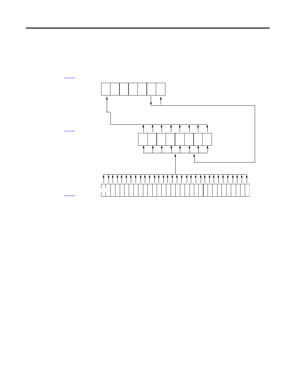
1756-IF8 Fault Reporting in
Integer Mode
The illustration is an example of the fault reporting process for the 1756-IF8
module in integer mode.
15
14
13
12
11
10
9
5
4
3
2
1
0
0
15 = AnalogGroupFault
10 = Calibrating
9 = Cal Fault
14, 13, 12, & 11 are not
used by 1756-IF8
31 = Ch0Underrange
30 = Ch0Overrange
29 = Ch1Underrange
28 = Ch1Overrange
27 = Ch2Underrange
26 = Ch2Overrange
25 = Ch3Underrange
24 = Ch3Overrange
41515
Underrange and overrange conditions
set the corresponding Channel Fault
word bit for that channel
When the module is
calibrating, all bits in the
Channel Fault word are set
If set, any bit in the Channel Fault word, also sets the Analog
Group Fault and Input Group Fault in the Module Fault word
A calibrating fault
sets bit 9 in the
Module Fault word
31
7
6
7 = Ch7Fault
6 = Ch6Fault
5 = Ch5Fault
4 = Ch4Fault
8 channels used in S.E. wiring
4 channels used in Diff. wiring
2 channels used in H.S. Diff. wiring
All start at bit 0
23 = Ch4Underrange
22 = Ch4Overrange
21 = Ch5Underrange
20 = Ch5Overrange
19 = Ch6Underrange
18 = Ch6Overrange
17 = Ch7Underrange
16 = Ch7Overrange
Eight channels used in S.E. wiring
Four channels used in Diff. wiring
Two channels used in H.S. Diff. wiring
All start at bit 31
Module Fault Word
(described on
)
Channel Fault Word
(described on
)
Channel Status Words
(described on
)
3 = Ch3Fault
2 = Ch2Fault
1 = Ch1Fault
0 = Ch0Fault