Rockwell Automation 1756-XXXX ControlLogix Analog I/O Modules User Manual
Page 346
346
Publication 1756-UM009C-EN-P - December 2010
Appendix C Use Ladder Logic To Perform Run Time Services and Reconfiguration
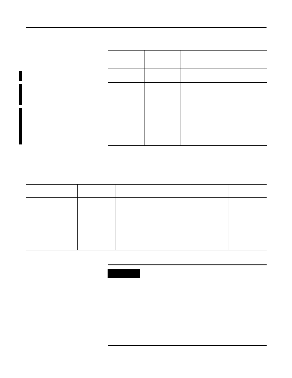
The following table contains input configuration information that is
necessary only
if you are configuring the message with RSLogix 5000
software, versions 9 or earlier.
Object Type
Class
Object that you are sending a message to, such
as the device object or a discrete output point.
Object ID
Instance
Each object can have multiple instances. For
example, a discrete output can have 16 points
or instances of where a message can be sent.
This specifies the instance.
Object Attribute
Attribute
Further identifies the exact address for the
message. An analog input can have multiple
alarms so this attribute acknowledges a
specific alarm and not the other alarms. If an
attribute is not specified (default to 0) the
Service applies to all attributes of the
Class/Instance.
Relationship of Message Configuration Parameters
RSLogix 5000
Versions 9
and earlier
RSLogix 5000
Versions 10
and later
Description
Analog Input Modules Configuration Dialog Window Information
Enter the following
To unlatch the
high high alarm
To unlatch the
high alarm
To unlatch the
low alarm
To unlatch the
low low alarm
To unlatch the
rate alarm
Service Code
4B
4B
4B
4B
4B
Object Type
0A
0A
0A
0A
0A
Object ID
(1)
(Channel Number)
1…6 or 1…8
1…6 or 1…8
1…6 or 1…8
1…6 or 1…8
1…6 or 1…8
Object Attribute
6E
6C
6B
6D
6F
Number of Elements
0 bytes
0 bytes
0 bytes
0 bytes
0 bytes
(1)
The 1756-IF16 module does not have any unlatchable features in the 16-channel mode.
IMPORTANT
For input or output modules, the Object Attribute determines
which alarm feature for the selected channel to unlatch. If this
field is left blank, all alarms for the selected channel will
be unlatched.
You must send separate message instructions to control
specific alarms on each channel of the module.
Also, Object ID represents channel number. For the 1756-IF6I,
1756-IR6I, and 1756-IT6I modules, channels 0…5 are
represented by Object ID 1…6. For the 1756-IF16 (in differential
mode only) and 1756-IF8 modules, channels 0…7 are
represented by Object ID 1…8.