P stc-2002, Deposition controller y – INFICON STC-2002 Thin Film Deposition Controller Operating Manual User Manual
Page 47
p STC-2002
DEPOSITION CONTROLLER
y
SECTION 2.XX
e page 45 of 276 ^
001:
I71 T67
002:
END
Starting with the above I/O program, the TRIP function is replaced with the OUTPUT function, and the
Boolean NOT operator is inserted between the Input and the Output tokens. With this I/O program
running, the LED is immediately illuminated. Pressing the rightmost key causes the rightmost LED to
extinguish. The key is considered a logical False (low) when not pressed. The logical False (low) is
converted to a logical True (high) by the Boolean NOT operator which is in turn sent to the LED output
thus illuminating it. Pressing the key is considered a logical True (high). The logical True (high) is
converted to a logical False (low) by the Boolean NOT operator which is in turn sent to the LED output
thus extinguishing it.
001:
I71 ! O67
002:
END
The following is an I/O program that uses elements of the previous two programs to demonstrate the
difference between the Trip and Output functions. Again, the I/O program inputs a user programmable
front panel key and outputs the logical state of the input to a user programmable front panel LED. The Trip
function will be pulsed whereas the Output function is not. If the 70 key is pressed and held, the 66 LED is
illuminated for about a second, it must be released and pressed again to illuminate the 66 LED once more.
If the 65 key is pressed and held, the 65 LED is illuminated for at least as long as the 65 key is held.
001:
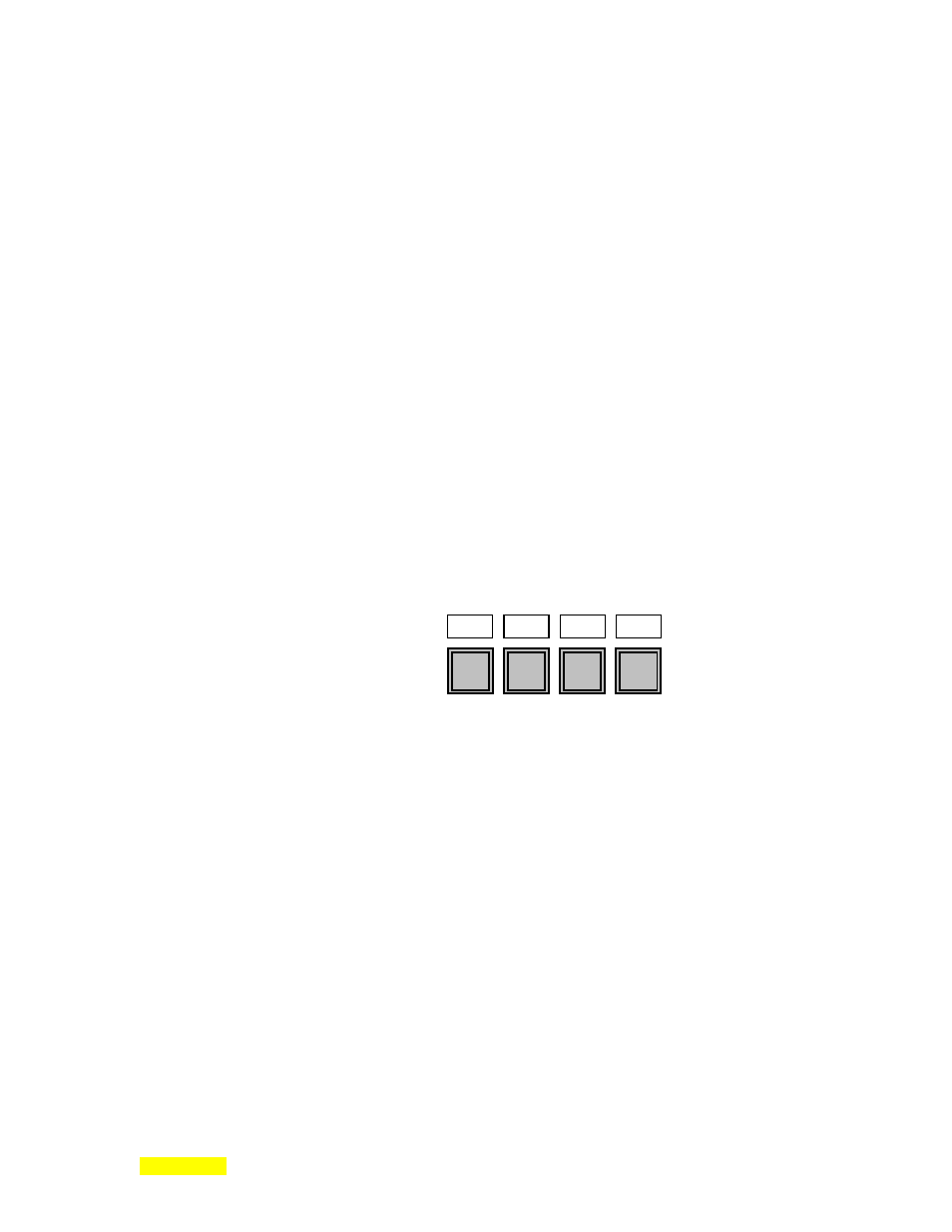
Front Panel Leds >
I70 T66
Trip
002:
I69 O65
Output
Front Panel Keys >
003:
END
The following program provides indications of 2 Stopped Mode conditions. The first should be activated
upon pressing the front panel STOP key (leftmost LED). The second LED is illuminated when a process
stops due to failed crystal when running a deposition (LED 2
nd
from the left). Please note that once the
leftmost LED is illuminated, it will not be off until the deposition process is run again. The next LED will
not be off until the deposition process is run again with the crystal replaced and re-verified (menu invoked
at the 2
nd
press of the STATUS Key). Input 73 is not a simple Boolean value as was 71 in the above
example but a scalar numeric value. In the first case (line 001), the Stopped Mode (73) is input and
compared to the constant numeric value of 4 by the EQUality operator. If the input is equal to the value of
4 then it will be passed on to the Output at 64 as a Boolean True. If it is not equal to 4, then it will be
passed on to the Output at 64 as a Boolean False. The LED will, in turn, indicate the result. Line 002 is
similar except that the input is checked against the constant numeric value of 2 and the result is output to a
different LED.
001:
I73 #4 = O64
⇐ inputs status of Stopped Mode from Front Panel. When true, LED = on
002:
I73 #2 = O65
⇐ inputs status of Stopped Mode-Crystal Bad. When true, LED = on
003:
END
64
65
66
67
68
KEY
69
KEY
70
KEY
71
KEY