Sensor head installation, P stc-2002, Deposition controller y – INFICON STC-2002 Thin Film Deposition Controller Operating Manual User Manual
Page 137: Electrical connections and descriptions, Figure- : 4.1 head mounting dimensions
p STC-2002
DEPOSITION CONTROLLER
y
SECTION 4.XX
e page 135 of 276 ^
Electrical Connections And Descriptions
SECTION 4.0
Sensor Head Installation
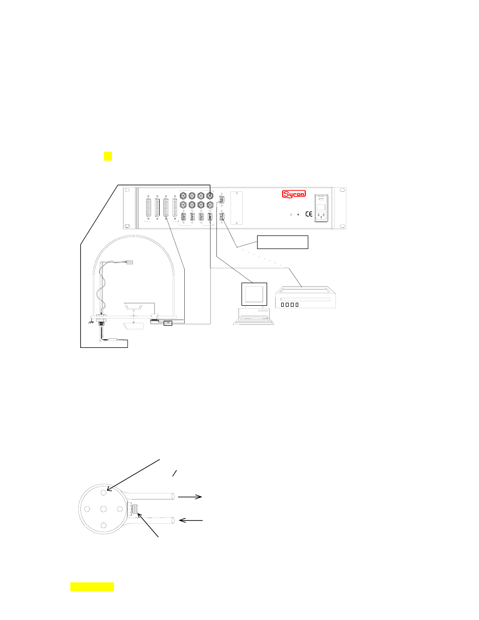
Following is a diagram of a typical evaporator installation. This diagram is repeated and described further
in Section x3 (see fig. 3.7).
CRYSTAL SENSOR
SHUTTER
DATA AQUISITION
COMPUTER
CHAMBER
DEPOSITION
SOURCE
OSCILLATOR
WARNING
!
The power cord protective
grounding conductor must be
connected to ground. No user
serviceable parts inside. Refer
servicing to qualified personnel.
FUSE: 2 x 2.00 AMP
QUICK-ACTING (F) 250v
90-264 vac, 50-60 Hz, 230VA MAX
INPUTS / OUTPUTS
SOURCE
SENSORS
I/O 4 1/O 3 I/O 2 I/O 1
COMM OPTION
RS232
MEM
instruments
Memory Module
7 5 3 1
8 6 4 2
CHART RECORDER
8 6 4 2
7 5 3 1
Sensor Installation
As a general rule the sensor head should not be installed closer than 10 inches to the evaporation
source. This minimum distance will generally provide adequate measurement sensitivity while reducing
the possibility of the source spattering small particles onto the sensor. Even small particles hitting the
crystal surface may cause the crystal to become unstable or stop oscillating completely.
The sensor should be shielded from the evaporant source by a shutter or other means when
evaporant material is being initially conditioned or outgassed.
Water Coolin
Microdot Coaxial Connec
#4-40 Tap -- 4 holes
Equally Spaced
on o0.731 B.C.
Figure- : 4.1 Head Mounting Dimensions.