P stc-2002, Deposition controller y, Hardware setup discussion – INFICON STC-2002 Thin Film Deposition Controller Operating Manual User Manual
Page 31
p STC-2002
DEPOSITION CONTROLLER
y
SECTION 2.XX
e page 29 of 276 ^
chooses the sensors that are part of the multiple sensor group. Since each sensor has a unique parameter
group, programming 2 or more crystals as active automatically invokes an averaging mode. Lost channels
during averaging are handled by menu programmed alternatives (Main Menu/Review SS Maps/Channel
Drop Filter Mask). TBD multiple sensor deposition: averaging multiple, averaging weight, interaction
calibration (among the crystal sensors) . [additive]
Although the STC-2002 cannot control multiple depositions (multiple sources as is the case with
co-deposition), but it can maintain other multiple sources (depending on installed and available sensor
cards) such that one source output is controlled while other source outputs can be maintained at a non-zero
power level. This would provide the ability to precondition other materials that could become activated
(controlled) when the currently controlled source reaches its preset conditions. In other words, multiple
source outputs can be providing some level of output to multiple power supplies while deposition control
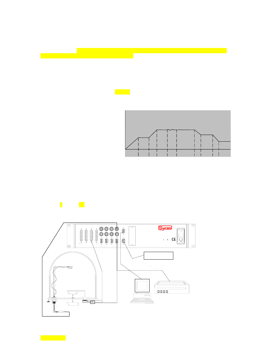
can be focused on a single source output (moved) among these. The preconditioning mentioned above
would include the soak phases of the deposition process cycle. The soak phase is (or soak phases are)
characterized by power being maintained at a constant level.
Note soak power levels in deposition cycle
Rise
1
Rise
2
Soak
1
Soak
2
Shutter
Delay
Deposit
Rate
Ramp
Deposit
2
Idle
Ramp
Idle
.
The more imaginative among us might, at this time, see an opportunity here to use the STC-2002 for a co-deposition process (set the
rate for a source output when active, select another source output as active and then allow the non-controlled output to deposit along
with the controlled output deposition). The problem with this scenario is in the shutter control that is linked to the active output
channel. Alternately, the shutter control could be accomplished with an I/O program but it would not control the process like a true co-
deposition unit nor would it have the same co-deposition oriented amenities
.
hardware setup discussion
(for actual installation details see Sections x3 & 4 but please read this section first)
.
necessities: crystal sensor head, osc, bnc cables, vacuum chamber, etc
.
Following is a diagram of a typical evaporator installation. This diagram is repeated and described further
in Section 3 (see fig. 3.7).
NOTE: Chart recorder function through memory module connection uses optional hardware and TBD software.
CRYSTAL SENSOR
SHUTTER
DATA AQUISITION
COMPUTER
CHAMBER
DEPOSITION
SOURCE
OSCILLATOR
WARNING
!
The power cord protective
grounding conductor must be
connected to ground. No user
serviceable parts inside. Refer
servicing to qualified personnel.
FUSE: 2 x 2.00 AMP
QUICK-ACTING (F) 250v
90-264 vac, 50-60 Hz, 230VA MAX
INPUTS / OUTPUTS
SOURCE
SENSORS
I/O 4 1/O 3 I/O 2 I/O 1
COMM OPTION
RS232
MEM
instruments
Memory Module
7 5 3 1
8 6 4 2
CHART RECORDER
8 6 4 2
7 5 3 1