5 diagram for state transition in standby mode, Diagram for state transition in standby mode – FUJITSU F2MC-8L F202RA User Manual
Page 84
68
CHAPTER 3 CPU
3.7.5
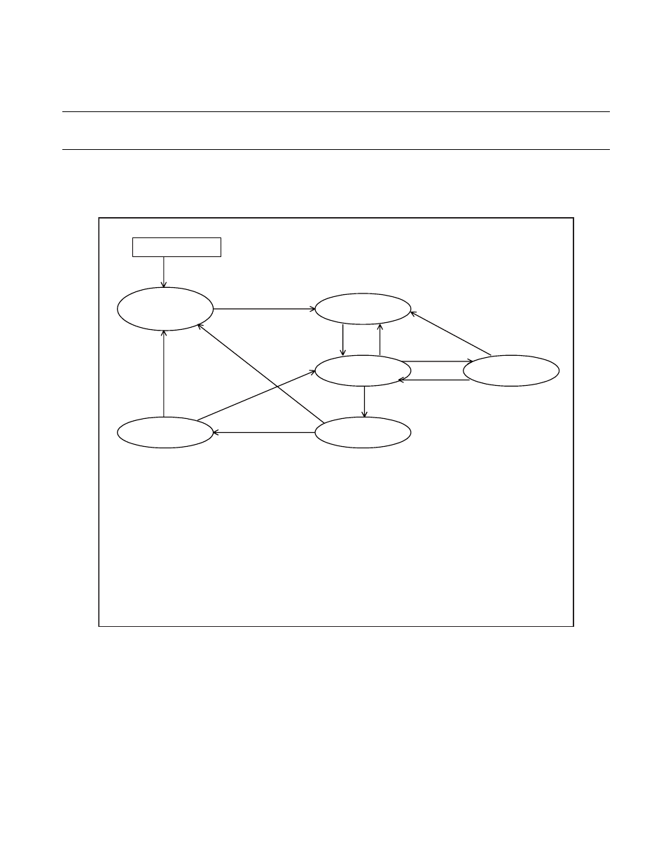
Diagram for State Transition in Standby Mode
Figure 3.7-2 shows the state transition diagram in standby mode.
■
Diagram for State Transition in Standby Mode
Figure 3.7-2 State Transition Diagram
Power t
u
rned on
Power-on re
s
et
O
s
cill
a
tion
s
t
ab
iliz
a
tion w
a
it
re
s
et mode
Re
s
et mode
RUN mode
S
leep mode
O
s
cill
a
tion
s
t
ab
iliz
a
tion w
a
it
S
top mode
(9)
(4)
(1)
(2)
(
3
)
(6)
(5)
(11)
(
8
)
(7)
(10)
(1)
: C
a
ncell
a
tion of re
s
et inp
u
t
(2)
(
3
)
(4)
(5)
(6)
(7)
(
8
) (9)
(10) (11)
: Re
s
et
s
o
u
rce
s
(m
u
ltiple)
: Tr
a
n
s
ition to
s
leep mode
b
y the
s
t
a
nd
b
y control regi
s
ter (
S
TBC:
S
LP = 1)
: Extern
a
l re
s
et inp
u
t
: Tr
a
n
s
ition to
s
top mode
b
y the
s
t
a
nd
b
y control regi
s
ter (
S
TBC:
S
TP = 1)
: Extern
a
l interr
u
pt re
qu
e
s
t
: Extern
a
l re
s
et inp
u
t
: Interr
u
pt re
qu
e
s
t
: Time-
bas
e timer overflow (end of o
s
cill
a
tion
s
t
ab
iliz
a
tion w
a
it time)