Bits for controlling acceptance of interrupts – FUJITSU F2MC-8L F202RA User Manual
Page 46
30
CHAPTER 3 CPU
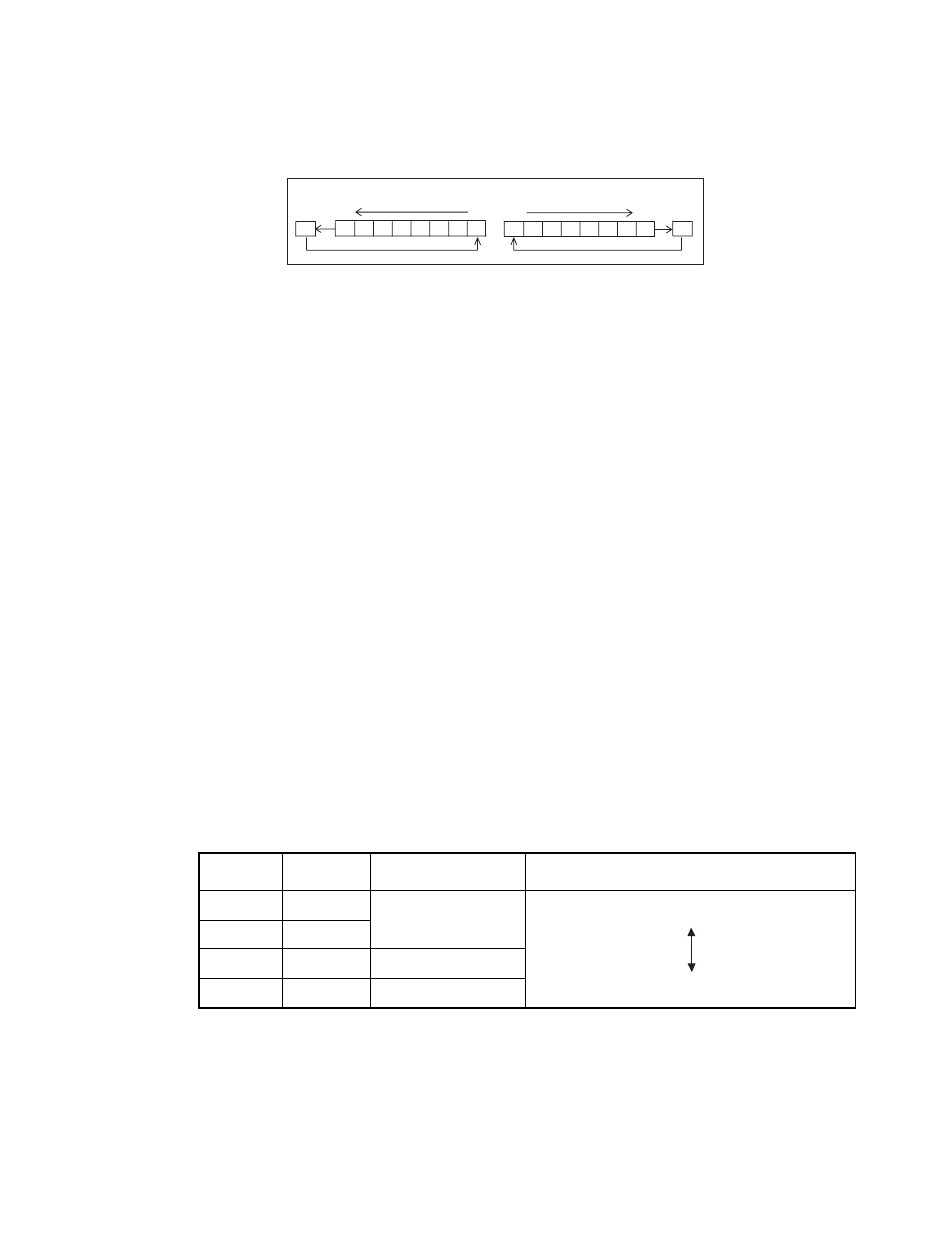
Figure 3.2-3 shows how the shift commands change the carry flag.
Figure 3.2-3 Change of the Carrier Flag by the Shift Commands
Note:
The condition code register is part of the program status register (PS), and thus is not allowed to access
only the condition code register.
It is uncommon to fetch and use only some of the flag bits directly. Normally, branch instructions (such as
BNZ) or decimal adjustment instructions (such as DAA and DAS) use them indirectly. The initial values of
these flags specified after the reset operation are undefined.
■
Bits for Controlling Acceptance of Interrupts
●
Interrupt enable flag (I)
When this flag is "1", interrupts are allowed and the CPU accepts interrupts.
When this flag is "0", interrupts are prohibited and the CPU does not accept interrupts.
The initial value of the interrupt enable flag after the reset operation is "0".
Normally, the SETI instruction sets the interrupt enable flag to "1", and the CLRI instruction sets it to "0"
to clear.
●
Interrupt level bits (IL1 and IL0)
These bits indicate the level of an interrupt the CPU is accepting, then it is compared with the values in the
interrupt level setting registers (ILR1 to 4) which is specified as the level of interrupt requests of peripheral
functions (IRQ0 to IRQF).
When the interrupt enable flag is turned on (I = 1), and if an interrupt is requested with an interrupt level
value lower than that of these bits, the CPU accepts the interrupt. Table 3.2-1 provides interrupt level
intensities. The initial value of the interrupt level specified after the reset operation is 11
B
.
Note:
When the CPU is not handling an interrupt (handling the main program), the interrupt level bits (IL1
and IL0) are normally set to 11
B
.
For details on interrupts, see Section "3.4 Interrupts ".
bit7
bit0
bit7
bit0
C
C
- Shift to the left (ROLC)
- Shift to the right (RORC)
Table 3.2-1 Interrupt Levels
IL1
IL0
Interrupt level
Intensity
0
0
1
High
Low (no interrupts allowed)
0
1
1
0
2
1
1
3