1 serial mode control register (smc), Serial mode control register (smc) – FUJITSU F2MC-8L F202RA User Manual
Page 306
290
CHAPTER 13 UART
13.4.1
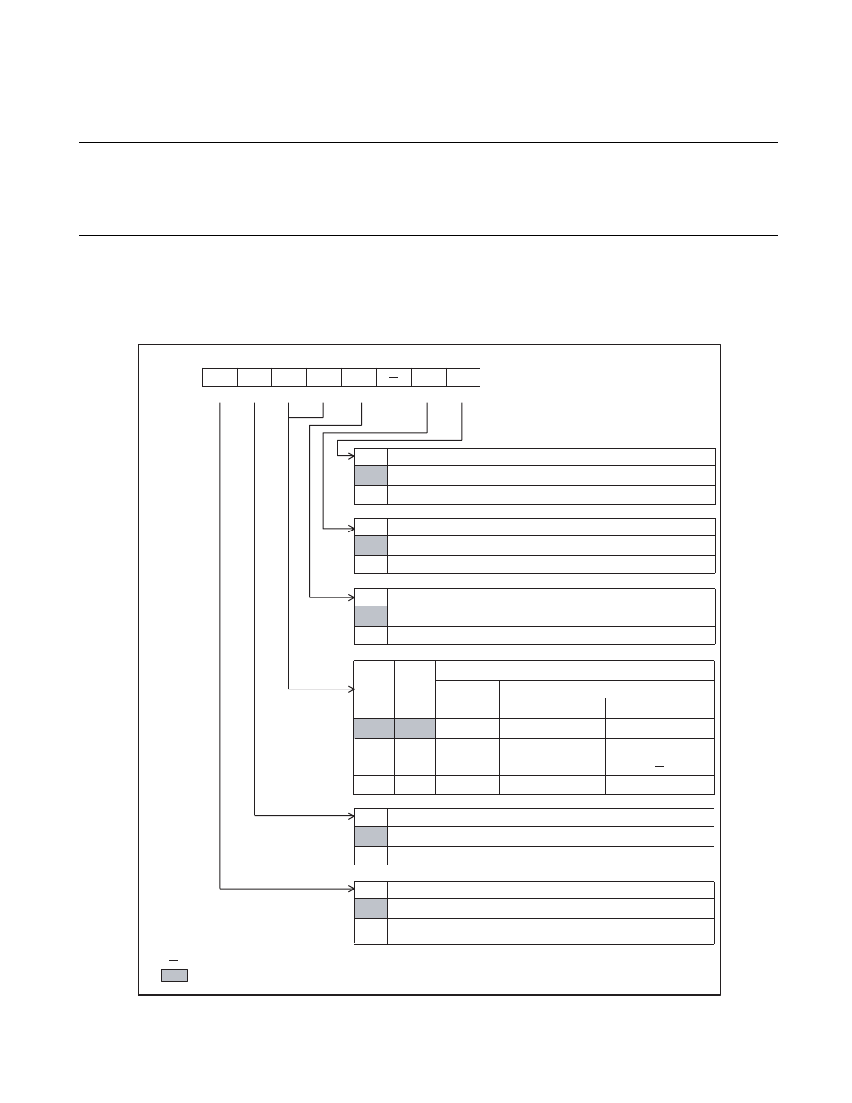
Serial Mode Control Register (SMC)
The serial mode control register (SMC) specifies the parity setting, stop bit length,
operating mode (data length), and synchronous/asynchronous mode, and enables/
disables UART serial clock output and serial data output.
■
Serial Mode Control Register (SMC)
Figure 13.4-2 Serial Mode Control Register (SMC)
S
OE
0
1
S
CKE
0
1
S
MDE
0
MC1
MC0
0
0
0
7
b
it
s
6
b
it
s
0
1
1
8
b
it
s
7
b
it
s
1
0
2
8
+1
b
it
s
1
1
3
9
b
it
s
8
b
it
s
S
BL
0
PEN
0
b
it7
b
it6
b
it5
b
it4
b
it
3
b
it2
b
it1
b
it0
002
8
H
PEN
S
BL
MC1
MC0
S
MDE
S
CKE
S
OE
00000-00
B
R/W
R/W
R/W
R/W
R/W
R/W
R/W
R/W : Re
a
d
ab
le/Writ
ab
le
: Un
us
ed
: Initi
a
l v
a
l
u
e
1
1
1
Addre
ss
Initi
a
l v
a
l
u
e
S
eri
a
l d
a
t
a
o
u
tp
u
t en
ab
le
b
it
Gener
a
l-p
u
rpo
s
e port or
8
-
b
it
s
eri
a
l I/O d
a
t
a
o
u
tp
u
t pin
UART
s
eri
a
l d
a
t
a
o
u
tp
u
t pin
Clock o
u
tp
u
t en
ab
le
b
it
Gener
a
l-p
u
rpo
s
e port or clock inp
u
t pin for UART/
8
-
b
it
s
eri
a
l I/O
UART clock o
u
tp
u
t pin
S
ynchroniz
a
tion mode
s
election
b
it
S
ynchrono
us
tr
a
n
s
fer mode
A
s
ynchrono
us
tr
a
n
s
fer mode
Oper
a
ting mode
s
election
b
it
s
Oper
a
ting
mode
D
a
t
a
written:
Witho
u
t p
a
rity
(PEN = 0)
With p
a
rity
(PEN = 1)
S
top
b
it length
s
election
b
it
2
b
it
s
1
b
it
P
a
rity en
ab
le
b
it
P
a
rity di
sab
led
P
a
rity en
ab
led (TD
8
/TP in the
SS
D regi
s
ter
a
llow
s
choice of
even/odd.)