4 serial input data register (sidr), Serial input data register (sidr) – FUJITSU F2MC-8L F202RA User Manual
Page 313
297
CHAPTER 13 UART
13.4.4
Serial Input Data Register (SIDR)
The serial input data register (SIDR) is for inputting (receiving) serial data.
■
Serial Input Data Register (SIDR)
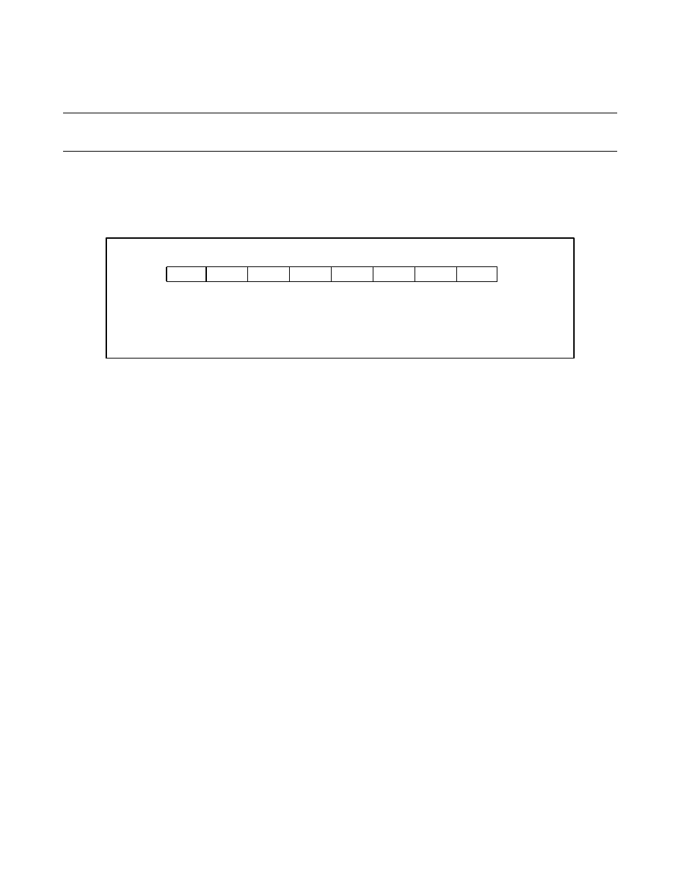
Figure 13.4-6 shows the configuration of the serial input data register bits.
Figure 13.4-6 Serial Input Data Register (SIDR)
The SIDR stores received data. The serial data input pin (UI pin) receives serial data signals, the shift
register converts them, then this register stores them.
●
When operating mode is 0, 1, or 3
For both the RDRF (Received data flag bit) and ORFE (Overrun/framing error flag bit), these flags go on
and an interrupt request to the CPU is generated when data is fully transmitted or received, then the stop bit
at the end is detected. When the RDRF is active, the data received is transmitted to the SIDR.
When the received data is correctly stored in this register, "1" is set for the received data flag bit (RDRF). If
the reception interrupt request is allowed, the reception interrupt is generated. When the RDRF bit has been
checked in interrupt processing or the program and the received data has been stored into this register, read
the contents in this register after reading the SSD register, then clear the RDRF flag.
●
When operating mode is 2
For both RDRF and ORFE, these flags go on when data is fully transmitted or received with the final data
bit (D8) set to "1" and the stop bit at the end is detected. However, when the framing error occurs, the flag
goes on regardless of the final data bit. An interrupt request to the CPU is generated when the flag goes on
and the interrupt request is allowed.
bit7
bit6
bit5
bit4
bit3
bit2
bit1
bit0
002B
H
XXXXXXXX
B
R
R
R
R
R
R
R
R
R
X
Address
Initial value
: Read only
: Undefined