2 serial rate control register (src), Serial rate control register (src) – FUJITSU F2MC-8L F202RA User Manual
Page 308
292
CHAPTER 13 UART
13.4.2
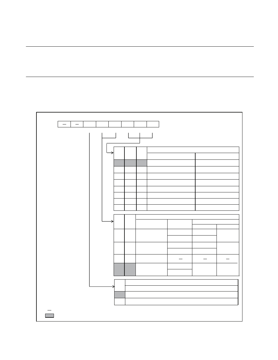
Serial Rate Control Register (SRC)
The serial rate control register (SRC) controls the data transfer rate (baud rate) in
asynchronous transfer mode. The SRC selects the input clock and sets the transfer rate
for the dedicated baud rate generator.
■
Serial Rate Control Register (SRC)
Figure 13.4-3 Serial Rate Control Register (SRC)
RC2 RC1 RC0
0
0
0
83
/12019
0.
8
/1.25M
0
0
1
166/6010
1.6/625k
0
1
0
333
/
3
005
3
.2/
3
1
3
k
0
1
1
666/150
3
6.4/156k
1
0
0
1
33
1/751
12.
8
/7
8
k
1
0
1
2662/
3
75
25.6/
3
9k
1
1
0
1
3
/7
8
125
1.6/625k
1
1
1
102/9766
12.
8
/7
8
k
C
S
1 C
S
0
0
16
0
0
1
64
1
0
16
0
1
1
64
2
1
0
0
1
1
1
8
1
CR
0
1
b
it7
b
it6
b
it5
b
it4
b
it
3
b
it2
b
it1
b
it0
0029
H
CR
C
S
1
C
S
0
RC2
RC1
RC0
--011000
B
R/W
R/W
R/W
R/W
R/W
R/W
R/W
Addre
ss
Initi
a
l v
a
l
u
e
B
au
d r
a
te
s
election
b
it
s
A
s
ynchrono
us
(
µ
s
/
bau
d)
S
ynchrono
us
(
µ
s
/
bau
d)
Clock inp
u
t
s
election
b
it
s
Clock inp
u
t
CR
b
it
Clock fre
qu
ency divider
A
s
ynchrono
us
S
ynchrono
us
Extern
a
l clock
PWM timer o
u
tp
u
t
Un
us
ed
Dedic
a
ted
bau
d
r
a
te gener
a
tor
Clock r
a
te inp
u
t
s
election
b
it
Effective only in
as
ynchrono
us
tr
a
n
s
fer mode (
S
MC:
S
MDE = 1)*
1/16 of the clock inp
u
t
1/64 of the clock inp
u
t
However, when the dedic
a
ted
bau
d r
a
te gener
a
tor i
s
us
ed (C
S
1
a
nd C
S
0 = 11
B
),
it i
s
fixed
a
t 1/
8
.
* :
: Re
a
d
ab
le/Writ
ab
le
: Initi
a
l v
a
l
u
e
: Un
us
ed