FUJITSU F2MC-8L F202RA User Manual
Page 99
83
CHAPTER 4 I/O PORTS
●
Operation in stop mode
When the pin state setting bit of the standby control register (STBC: SPL) is "1" and when the stop mode is
entered, the output transistor is turned OFF and the pin becomes Hi-Z because the output transistor is
forcibly turned OFF without respect to the value existing on the DDR0 register in the bit position
corresponding to the pin.
Input remains fixed to prevent leaks by input open.
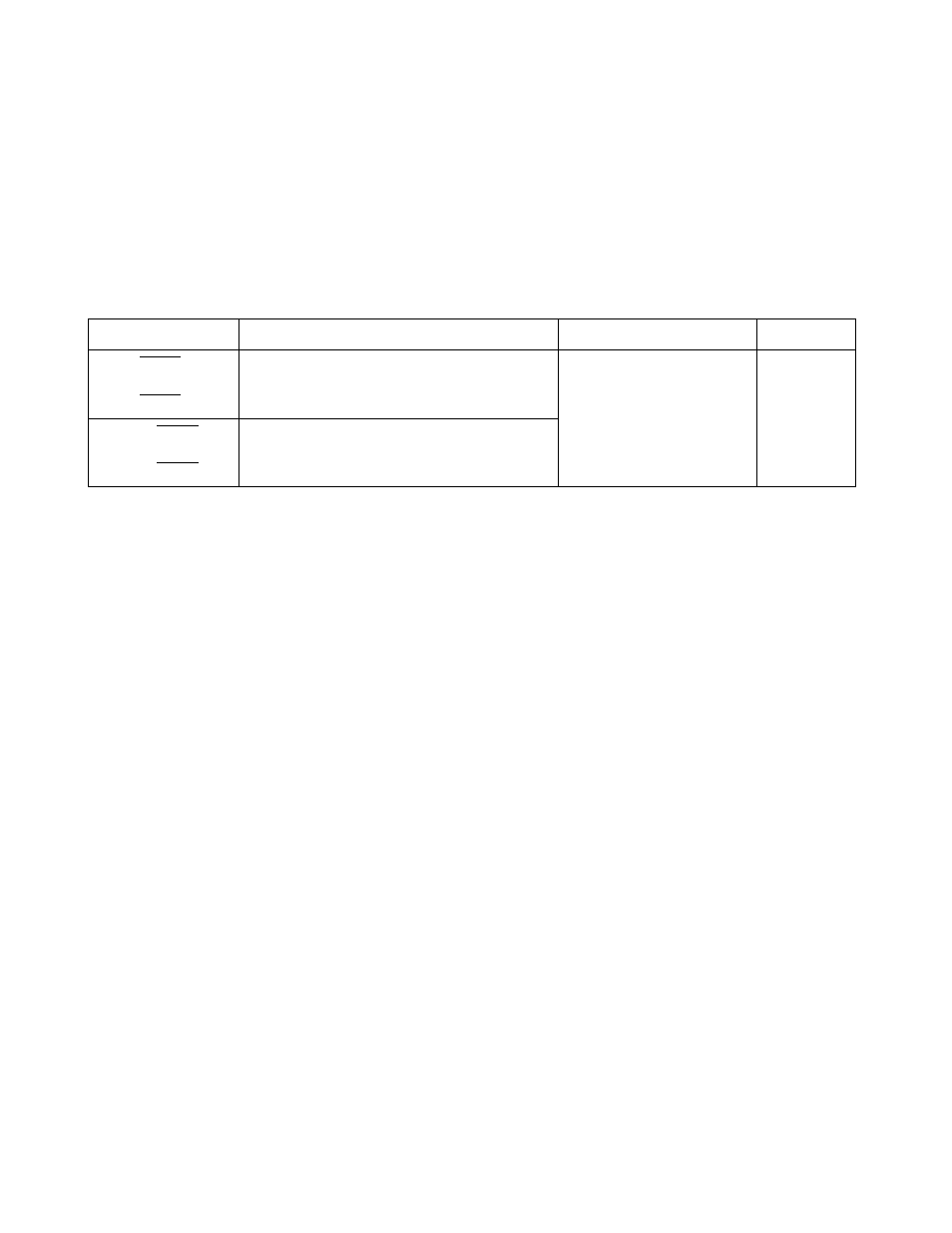
Table 4.2-4 summarizes the operating modes of the pins of port 0.
Note:
When the pull-up resistor is selected by using the pull-up setting register, the pin state will be "H" level
instead of Hi-Z in stop mode (SPL = 1). During a reset, however, the pull-up is invalid with the pin
remaining at Hi-Z.
Table 4.2-4 Operating Modes of Pins of Port 0
Pin name
Normal operation, sleep, stop (SPL = 0)
Stop (SPL = 1)
At a reset
P00/INT20/AN4
to
P03/INT23/AN7
General-purpose I/O port may also serve
external interrupt inputs or analog inputs
Hi-Z
(External interrupt input)
Hi-Z
P04/INT24
to
P07/INT27
General-purpose I/O port may also serve
external interrupt inputs
SPL : Pin state setting bit of standby control register (STBC: SPL)
Hi-Z: High impedance