8 i/o circuit types, I/o circuit types – FUJITSU F2MC-8L F202RA User Manual
Page 30
14
CHAPTER 1 OVERVIEW
1.8
I/O Circuit Types
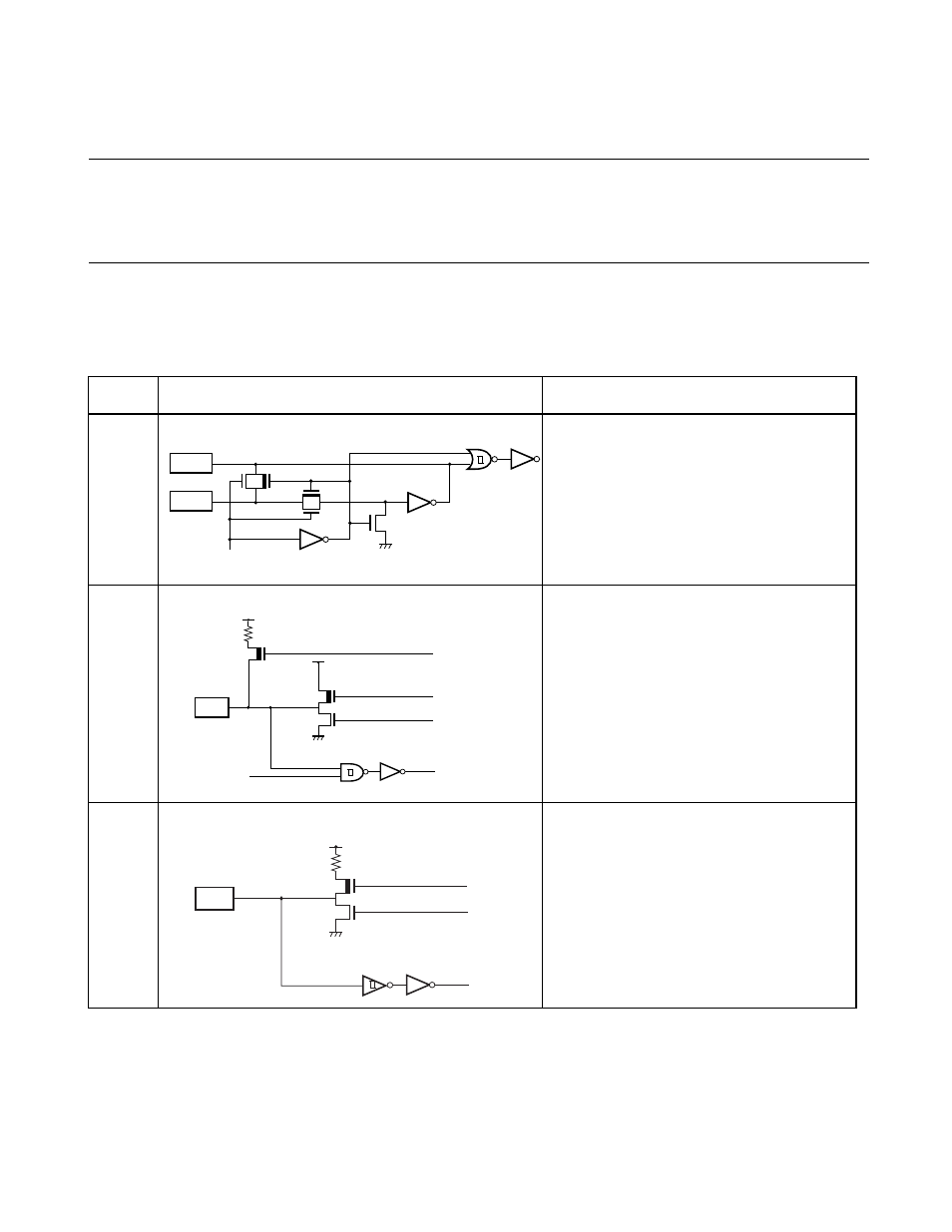
Table 1.8-1 describes the I/O circuit types.
The letters in the circuit column shown in Table 1.8-1 correspond to the letters in the
circuit type column shown in Table 1.7-1 .
■
I/O Circuit Types
Table 1.8-1 I/O Circuit Types (1/2)
Types
Circuit
Remarks
A
At an oscillation feedback resistance of
approximately 500 k
Ω
B
CMOS output
Hysteresis input
Pull-up resistor optional
C
At an output pull-up resistor (P-ch) of
approximately 50 k
Ω/5.0 V
(not available for MB89F202/F202RA)
N-ch open-drain reset output
Hysteresis input
High voltage input tolerable in MB90F202RA
X1
Standby control signal
X0
P-ch
N-ch
P-ch
Input enable
Port / Resource
P-ch with p
u
ll-
u
p, not
a
v
a
il
ab
le for
MB
8
9F202/F202RA
N-ch
Re
s
et
This manual is related to the following products: