5 interrupt of 8-bit pwm timer, Interrupt of 8-bit pwm timer – FUJITSU F2MC-8L F202RA User Manual
Page 163
147
CHAPTER 7 8-BIT PWM TIMER
7.5
Interrupt of 8-bit PWM Timer
An interrupt factor of an 8-bit PWM timer can be a match between the counter value and
the PWM compare register value while interval timer functions are operating. While the
PWM timer functions are enabled, an interrupt request does not occur.
■
Interrupts while Interval Timer Functions are Enabled
When the counter value is incremented from 00
H
using the selected count clock and matches the PWM
compare register (COMR) value, "1" is set to the corresponding interrupt request flag bit (CNTR: TIR).
At this time, if the bit to enable an interrupt request is enabled (CNTR: TIE = 1), an interrupt request
(IRQ9) to the CPU occurs. Write "0" to the TIR bit using the interrupt handling routine to clear the
interrupt request.
The TIR bit is set to "1" when the counter value matches the settings regardless of the value of the TIE bit.
Note:
When a match is found between the counter value and the COMR register value concurrently with the
stop of the counter (CNTR: TPE = 0), the TIR bit is not set.
When the TIR bit is "1", if the TIE bit is changed from disabled to enabled (changed from "0" to "1"),
an interrupt request occurs immediately.
■
Register and Vector Table Related to the Interrupts of an 8-bit PWM Timer
See Section "3.4.2 Steps in the Interrupt Operation
"
for interrupt operations.
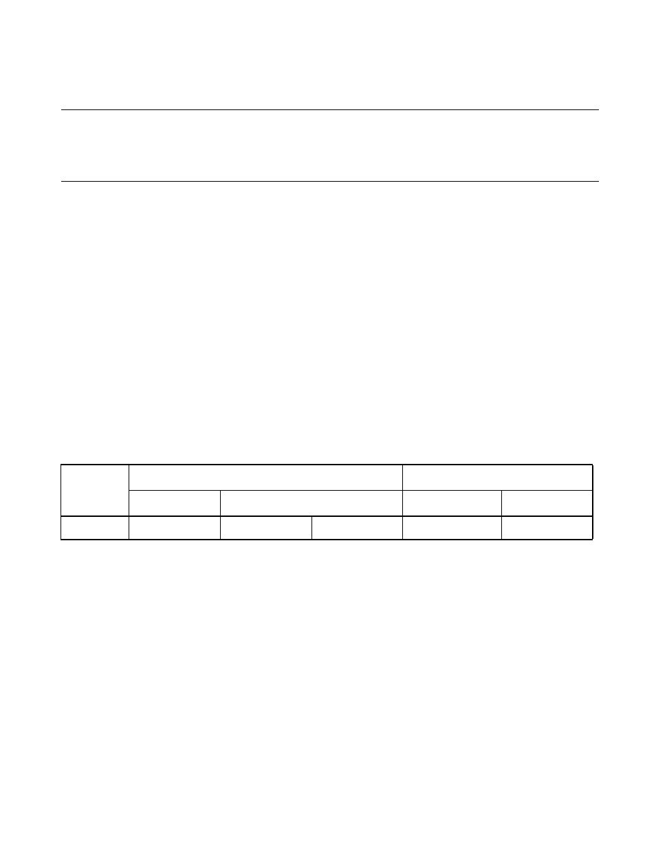
Table 7.5-1 Register and Vector Table Related to the Interrupts of an 8-bit PWM Timer
Interrupt
name
Interrupt level setting register
Address of vector table
Register
Bits to be set
High-order
Low-order
IRQ9
ILR3(007D
H
)
L91(bit3)
L90(bit2)
FFE8
H
FFE9
H