1 external interrupt control register 1 (eic1), External interrupt control register 1 (eic1) – FUJITSU F2MC-8L F202RA User Manual
Page 248
232
CHAPTER 10 EXTERNAL INTERRUPT CIRCUIT 1 (EDGE)
10.4.1
External Interrupt Control Register 1 (EIC1)
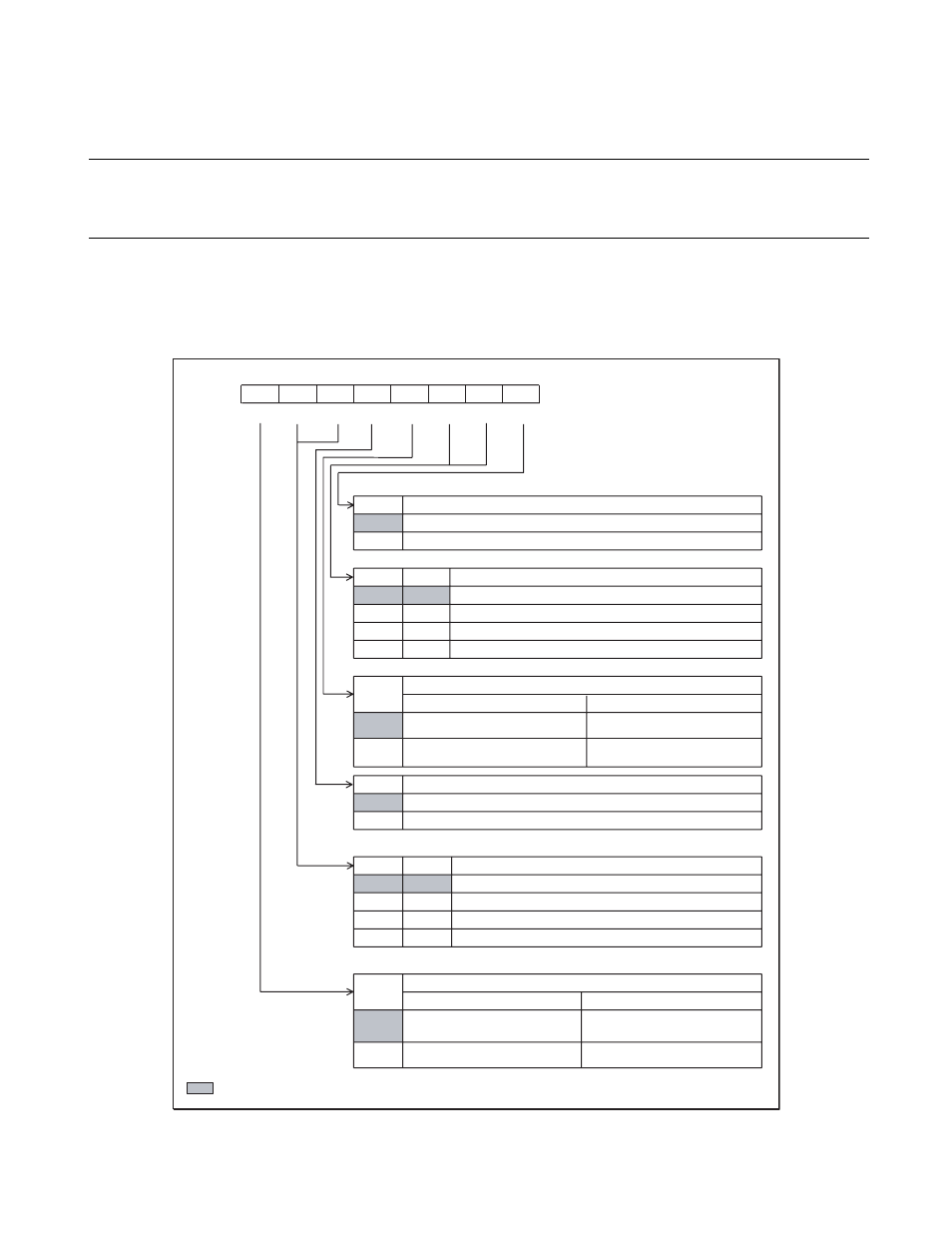
External interrupt control register 1 (EIC1) comprises bits for edge polarity selection
and interrupt control for the INT10 and INT11 external interrupt pins.
■
External Interrupt Control Register 1 (EIC1)
Figure 10.4-2 External Interrupt Control Register 1 (EIC1)
EIE0
0
1
SL01
SL00
0
0
0
1
1
0
1
1
EIR0
0
1
EIE1
0
1
SL11
SL10
0
0
0
1
1
0
1
1
EIR1
0
1
bit7
bit6
bit5
bit4
bit3
bit2
bit1
bit0
0024
H
EIR1
SL11 SL10
EIE1 EIR0
SL01 SL00 EIE0
00000000
B
R/W
R/W
R/W
R/W
R/W
R/W
R/W
R/W
R/W : Readable/Writable
: Initial value
Address
Initial value
Interrupt request enable bit 0
Disables interrupt request outputs
Enables interrupt request outputs
Edge polarity selection bits 0
Edge detection OFF
Rising edge
Falling edge
Both edges
External interrupt request flag bit 0
When being read
When being written
Signal input with specified edge
or edges not detected
This bit is cleared
Signal input with specified edge
or edges detected
No change, does not affect other
operations
Interrupt request enable bit 1
Disables interrupt request outputs
Enables interrupt request outputs
Edge polarity selection bits 1
Edge detection OFF
Rising edge
Falling edge
Both edges
External interrupt request flag bit 1
When being read
When being written
Signal input with specified edge
or edges not detected
This bit is cleared
Signal input with specified edge
or edges detected
No change, does not affect other
operations