2 configuration of the buzzer output, Configuration of the buzzer output, Block diagram of the buzzer output – FUJITSU F2MC-8L F202RA User Manual
Page 357
341
CHAPTER 15 BUZZER OUTPUT
15.2
Configuration of the Buzzer Output
The buzzer output consists of the following two blocks:
• Buzzer output selector
• Buzzer register (BZCR)
■
Block Diagram of the Buzzer Output
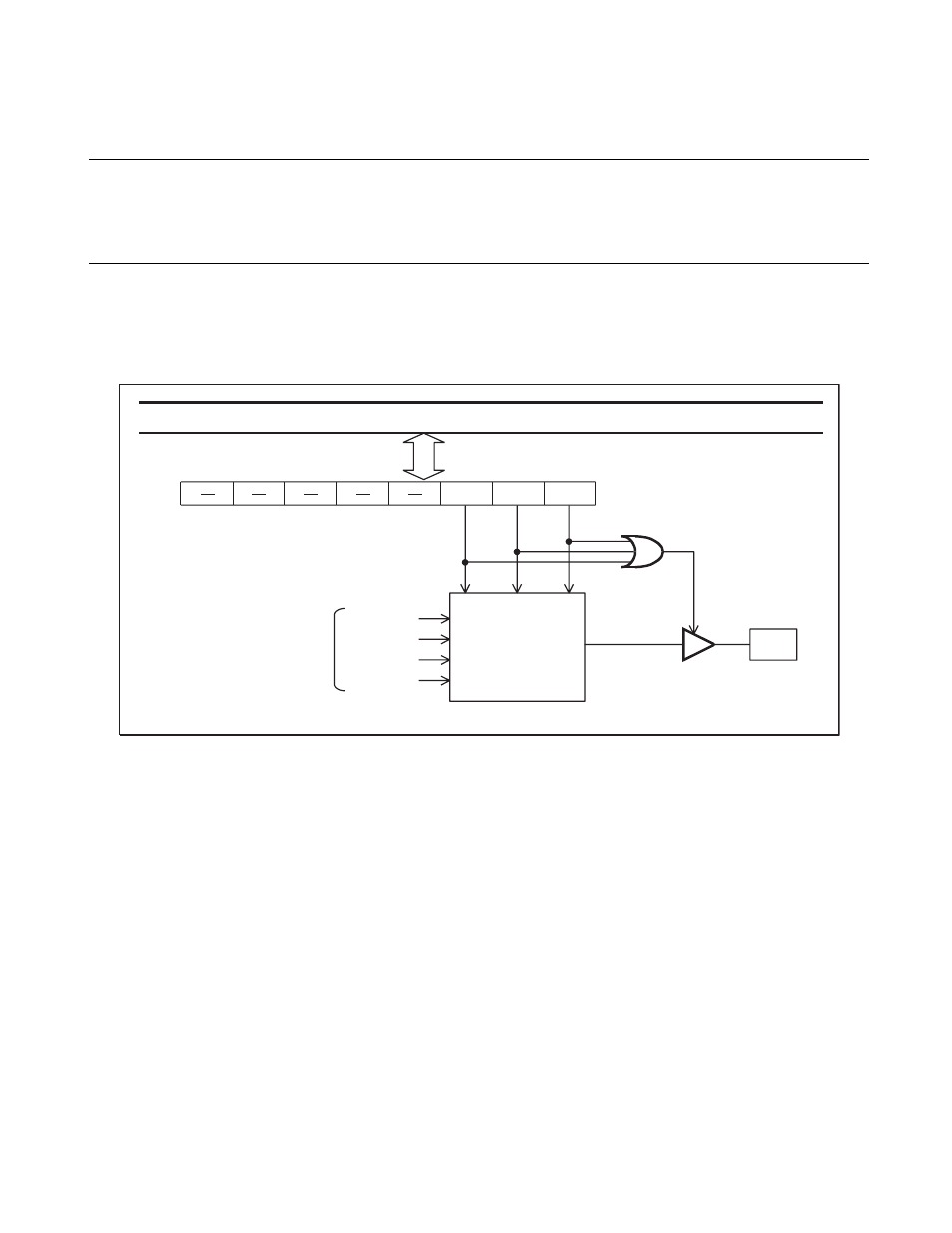
Figure 15.2-1 Block Diagram of Buzzer Output
●
Buzzer output selector
The buzzer output selector is a circuit for selecting one of the four frequencies (square waves) output from
the time-base timer. The buzzer register (BZCR) sets it.
●
Buzzer register (BZCR)
The buzzer register (BZCR) is a register for setting the buzzer output frequency and enable the buzzer
output. When the BZCR register sets an output frequency (other than 000
B
), the buzzer output is enabled so
that the P37/BZ/PPG pin automatically becomes the buzzer output (BZ) pin. Even if the PPG pin has been
enabled, the BZ pin has higher priority.
F
CH
BZ2
BZ1
BZ0
BZCR
P
3
7/BZ/PPG
2 1
3
/F
CH
2 12/F
CH
2 11/F
CH
2 10/F
CH
Intern
a
l d
a
t
a
bus
From time-
bas
e timer
B
u
zzer o
u
tp
u
t
s
elector
S
elector
o
u
tp
u
t
B
u
zzer en
ab
le
s
ign
a
l
Pin
: O
s
cill
a
tion fre
qu
ency