2 configuration of 12-bit ppg timer circuit, Configuration of 12-bit ppg timer circuit, Block diagram of 12-bit ppg timer – FUJITSU F2MC-8L F202RA User Manual
Page 225
209
CHAPTER 9 12-BIT PPG TIMER
9.2
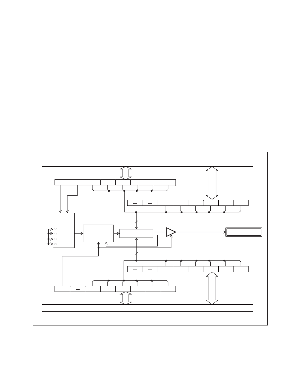
Configuration of 12-bit PPG Timer Circuit
The 12-bit PPG timer comprises the following seven blocks:
• Count clock selector
• 12-bit counter
• Comparator
• 12-bit PPG control register 1 (RCR21)
• 12-bit PPG control register 2 (RCR22)
• 12-bit PPG control register 3 (RCR23)
• 12-bit PPG control register 4 (RCR24)
■
Block Diagram of 12-bit PPG Timer
Figure 9.2-1 Block Diagram of 12-bit PPG Timer
: Instruction cycle
RCK1
RCK0 HSC5
HSC4
HSC3
HSC2
HSC1
HSC0
HSC11 HSC10 HSC9
HSC8
HSC7 HSC6
SCL11 SCL10
SCL9
SCL8
SCL7
SCL6
RCEN
SCL5
SCL4
SCL3
SCL2
SCL1
SCL0
CLK
2
4
16
256
12
12
1t
INST
RCR21
RCR22
RCR24
RCR23
t
INST
Internal data bus
Count
clock
selector
12-bit counter
Clear
Comparator
Compare value for "H" width
P37/BZ/PPG pin
Compare value for cycle period
Internal data bus