FUJITSU F2MC-8L F202RA User Manual
Page 126
110
CHAPTER 4 I/O PORTS
●
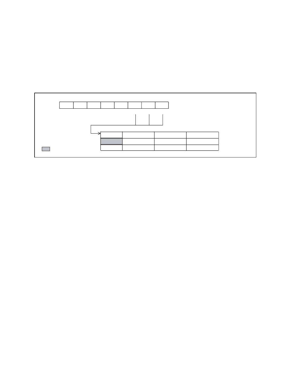
Port 7 pull-up setting register (PUL7)
The bits of the pull-up setting register correspond to the pins of port 7 in one-to-one correspondence.
When the pull-up resistor is selected by using the pull-up setting register, the pin will be at "H" level
(pull-up state) instead of Hi-Z during stop (SPL = 1). During a reset, however, the pull-up is invalid and
the pin remains at Hi-Z.
Figure 4.7-2 shows the pull-up resistor settings assigned to the values of the bits of the port 7 pull-up
register.
Figure 4.7-2 Pull-up Resistor Settings (PUL7)
PUL72
PUL71
PUL70
0
1
bit7
bit6
bit5
bit4
bit3
bit2
bit1
bit0
0065
H
-
-
-
-
-
PUL72 PUL71 PUL70
-----000
B
-
-
-
-
-
R/W
R/W
R/W
R/W
Address
Initial value
P72 pull-up OFF
P71 pull-up OFF
P70 pull-up OFF
P72 pull-up ON
P71 pull-up ON
P70 pull-up ON
: Readable/Writable
: Initial value