2 timer 0 control register (tcr0), Timer 0 control register (tcr0) – FUJITSU F2MC-8L F202RA User Manual
Page 189
173
CHAPTER 8 8/16-BIT CAPTURE TIMER/COUNTER
8.4.2
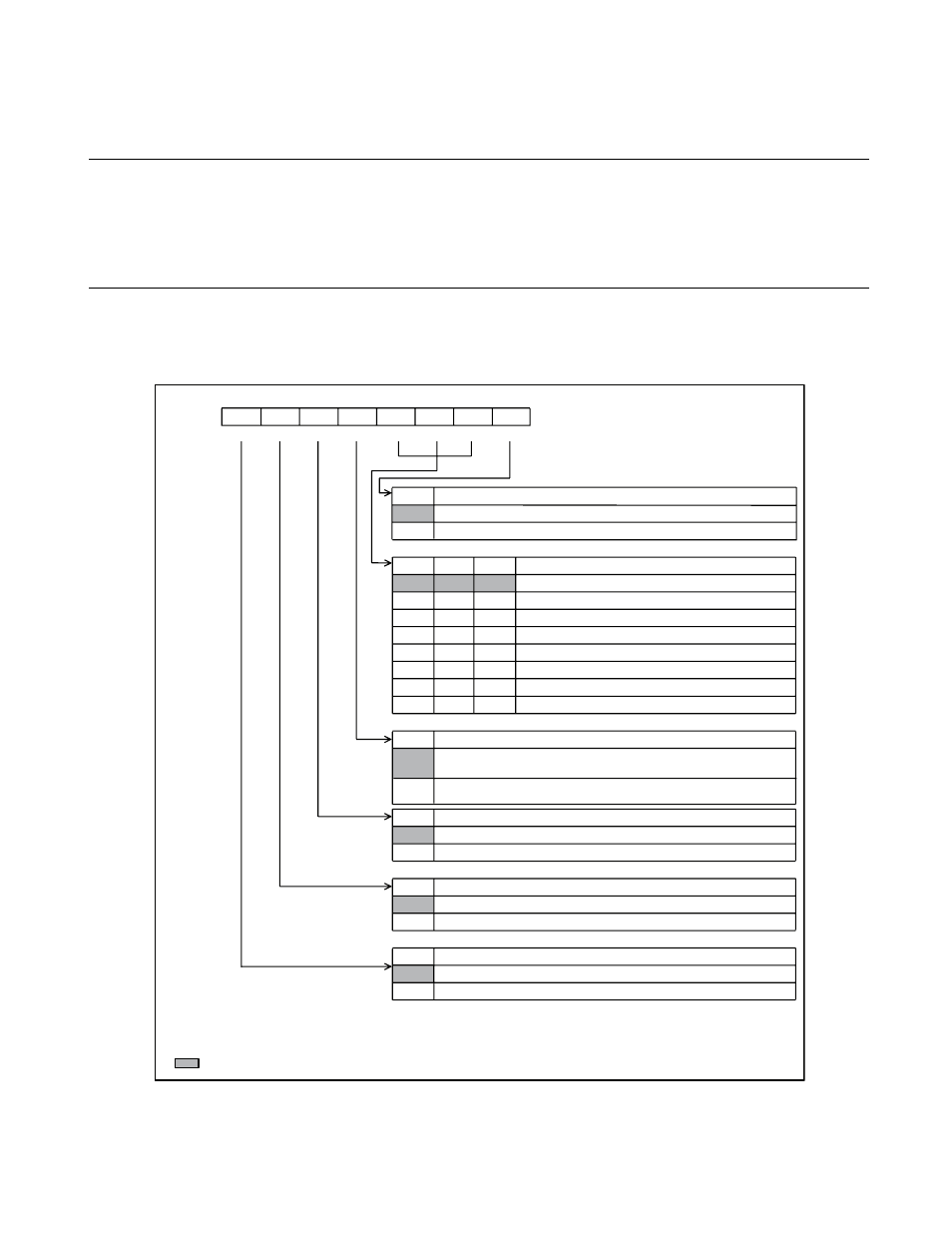
Timer 0 Control Register (TCR0)
The timer 0 control register (TCR0) is used to select functions, allow and prohibit
operation, control interrupts, and check interrupt states in timer 0 for the 8-bit mode of
the 8/16-bit capture timer/counter or in the 16-bit mode. Even if only timer 0 is used in
the 8-bit mode, the timer 1 control register (TCR1) must be initialized.
■
Timer 0 Control Register (TCR0)
Figure 8.4-3 Timer 0 Control Register (TCR0)
12
8
t
IN
S
T
[40.96
µ
s
]
16t
IN
S
T
[5.12
µ
s
]
0
TC
S
02 TC
S
01 TC
S
00
0
0
0
0
0
1
0
1
0
0
1
1
1
0
0
1
0
1
1
1
0
1
1
1
CINV
0
1
T0IEN
0
1
TFCR0
0
TIF0
0
b
it7
b
it6
b
it5
b
it4
b
it
3
b
it2
b
it1
b
it0
TIF0
TFCR0 T0IEN
CINV
TC
S
02 TC
S
01 TC
S
00 T
S
TR0
R
R/W
R/W
R/W
R/W
R/W
R/W
R/W
R/W : Re
a
d
ab
le/Writ
ab
le
R
: Re
a
d only
: Initi
a
l v
a
l
u
e
1
1
T
S
TR0
Addre
ss
Initi
a
l v
a
l
u
e
Timer
s
t
a
rt
b
it
The co
u
nter oper
a
tion i
s
s
topped.
The co
u
nter i
s
cle
a
red
a
nd increment
s
t
a
rt
s
.
Clock
s
o
u
rce
s
election
b
it
s
(o
s
cill
a
tion: 12.5 MHz)
Extern
a
l clock
Co
u
nt clock
s
election
b
it
The co
u
nter i
s
incremented
a
t the f
a
lling edge of
a
s
elected
clock
s
o
u
rce.
The co
u
nter i
s
incremented
a
t the ri
s
ing edge of
a
s
elected
clock
s
o
u
rce.
Interr
u
pt re
qu
e
s
t en
ab
le
b
it
Interr
u
pt re
qu
e
s
t o
u
tp
u
t i
s
prohi
b
ited.
Interr
u
pt re
qu
e
s
t o
u
tp
u
t i
s
a
llowed.
Comp
a
re m
a
tch detection fl
a
g cle
a
r
b
it
Not
a
ffected (
a
t re
a
d,
a
lw
a
y
s
"0")
The comp
a
re m
a
tch detection fl
a
g i
s
cle
a
red.
Comp
a
re m
a
tch detection fl
a
g
b
it
No comp
a
re m
a
tch h
as
occ
u
rred.
A comp
a
re m
a
tch occ
u
rred.
001B
H
00000000
B
2t
IN
S
T
[0.64
µ
s
]
4t
IN
S
T
[1.2
8
µ
s
]
64t
IN
S
T
[20.4
8
µ
s
]
256t
IN
S
T
[
8
1.92
µ
s
]
512t
IN
S
T
[16
3
.
8
4
µ
s
]
t
IN
S
T
: In
s
tr
u
ction cycle (Affected
b
y the clock mode
a
nd other
s
.)
1