FUJITSU F2MC-8L F202RA User Manual
Page 167
151
CHAPTER 7 8-BIT PWM TIMER
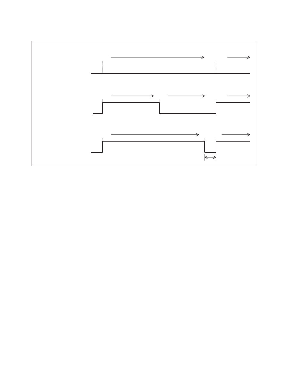
Figure 7.7-2 Output Example of the PWM Waveform of 8-bit PWM Timer Functions
Notes:
• While PWM timer functions are enabled (CNTR: TPE = 1), do not change the count clock cycle
(CNTR: P1, P0).
• While PWM timer functions are enabled, the level immediately before the stop is held as the output
level of the PWM pin in the counter stop state (CNTR: TPE = 0).
FF
H
00
H
00
H
"L"
"H"
00
H
FF
H
00
H
FF
H
00
H
80
H
"L"
"H"
"L"
"H"
00
H
When the COMR Register Value is 00
H
(0% duty ratio):
Counter value
PWM waveform
When the COMR register value is 80
H
(50% duty ratio):
When the COMR register value is FF
H
(99.6% duty ratio):
Counter value
PWM waveform
Counter value
PWM waveform
For one count
This manual is related to the following products: