2 configuration of time-base timer, Configuration of time-base timer, Block diagram of time-base timer – FUJITSU F2MC-8L F202RA User Manual
Page 134: 118 chapter 5 time-base timer
118
CHAPTER 5 TIME-BASE TIMER
5.2
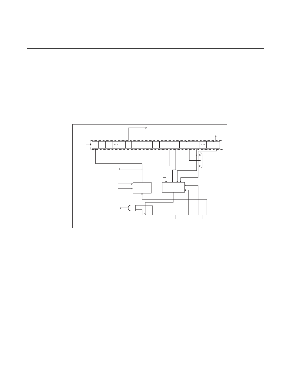
Configuration of Time-base Timer
The time-base timer consists of the following four function blocks.
• Time-base counter
• Counter clear circuit
• Interval timer selector
• Time-base timer control register (TBTC)
■
Block Diagram of Time-base Timer
Figure 5.2-1 Block Diagram of Time-base Timer
●
Time-base timer counter
A 21-bit up counter that accepts the oscillation frequency divided by two as the count clock and stops
operating when oscillation stops.
●
Counter clear circuit
Clears the counter when the TBTC register is set (TBR = 0), stop mode is entered (STBC: STP = 1), or a
power-on reset occurs.
●
Interval timer selector
Selects 1 bit for the interval timer from four bits in the time-base counter. When the specified bit overflows,
an interrupt occurs.
●
Time-base timer control register (TBTC)
Selects a time interval, clears the counter, controls interrupts, or checks the status.
TB0F TBIE
TBC1 TBC0 TBR
OF
OF
OF
OF
F
CH
:
O
s
cill
a
tion fre
qu
ency
X2
1
Time-
bas
e timer co
u
nter
X2
2
X2
3
X2
6
X2
7
X2
8
X2
9
X2
10
X2
11
X2
12
X2
1
3
X2
14
X2
15
X2
16
X2
17
X2
20
X2
21
To A/D converter
To w
a
tchdog timer
F
CH
divided
b
y two
Cle
a
ring co
u
nter
To clock control
s
ection o
s
cill
a
tion
s
t
ab
iliz
a
tion time
s
elector
Cle
a
ring w
a
tchdog timer
Power-on re
s
et
S
t
a
rting
s
top mode
(in norm
a
l mode)
Co
u
nter
cle
a
r
circ
u
it
Interv
a
l timer
s
elector
IRQ7 (time-
bas
e timer interr
u
pt)
OF: Overflow
Time-
bas
e timer control regi
s
ter (TBTC)