4 interrupts, Interrupts, N "3.4 interrupts ", sect – FUJITSU F2MC-8L F202RA User Manual
Page 50: Interrupt requests from peripheral functions
34
CHAPTER 3 CPU
3.4
Interrupts
The MB89202/F202RA series supports 12 interrupt request inputs corresponding to
peripheral functions and allows an interrupt level to be assigned to each of the inputs.
The interrupt controller compares levels of interrupts generated by peripheral functions
when output of interrupt requests is allowed for peripheral functions. The CPU performs
the interrupt operation according to its interrupt acceptance settings. The CPU cancels
standby mode on reception of an interrupt request, then returns to the interrupt
operation or normal operation.
■
Interrupt Requests from Peripheral Functions
Table 3.4-1 lists the interrupt requests that correspond to peripheral functions. When the CPU accepts an
interrupt, the CPU takes a branch to the interrupt processing routine using the address in the interrupt
vector table corresponding to the interrupt request as the branch address.
The interrupt level setting registers (ILR1, 2, 3, and 4) allow one of four interrupt processing intensities to
be assigned to each interrupt request.
Interrupt requests with levels equal to or less than that of an interrupt request being handled in the interrupt
processing routine are usually handled after the current interrupt processing routine ends. If interrupt
requests with the same assigned level are generated simultaneously, IRQ0 has priority.
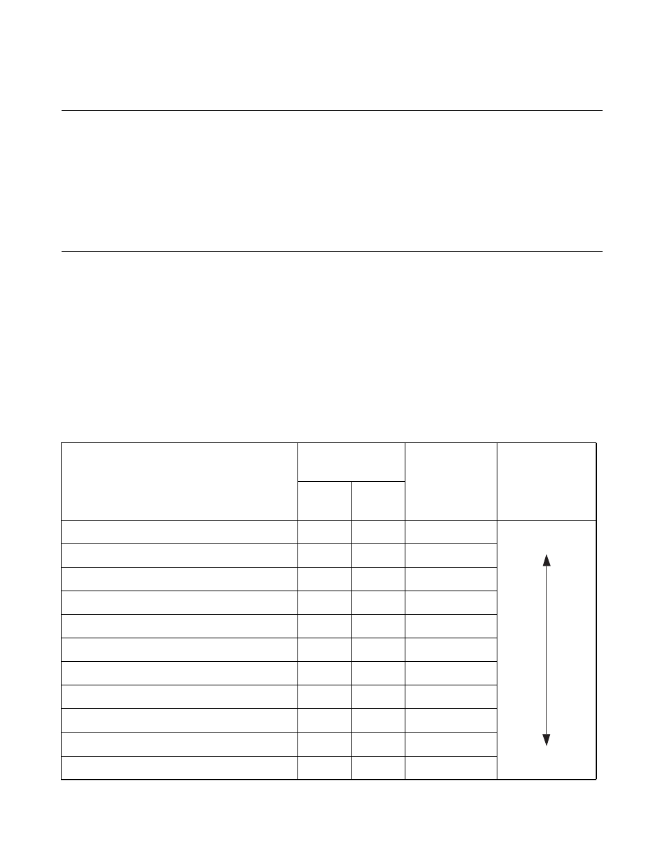
Table 3.4-1 Interrupt Requests and Interrupt Vectors (1/2)
Interrupt request
Address in the
vector table
Names of bits in
the interrupt
level setting
registers
Priority at
identical level (at
simultaneous
occurrence)
Upper
digits
Lower
digits
IRQ0 (External interrupt INT10)
FFFA
H
FFFB
H
L01, L00
High
Low
IRQ1 (External interrupt INT11)
FFF8
H
FFF9
H
L11, L10
IRQ2 (External interrupt INT12)
FFF6
H
FFF7
H
L21, L20
IRQ3 (8/16-bit capture timer/counter’s timer)
FFF4
H
FFF5
H
L31, L30
IRQ4 (8/16-bit capture timer/counter’s capture)
FFF2
H
FFF3
H
L41, L40
IRQ5 (Transmission with UART)
FFF0
H
FFF1
H
L51, L50
IRQ6 (Reception with UART)
FFEE
H
FFEF
H
L61, L60
IRQ7 (Time-base timer)
FFEC
H
FFED
H
L71, L70
IRQ8 (A/D converter)
FFEA
H
FFEB
H
L81, L80
IRQ9 (8-bit PWM)
FFE8
H
FFE9
H
L91, L90
IRQA (External interrupt 2)
FFE6
H
FFE7
H
LA1, LA0