10 notes on using 8/16-bit capture timer/counter, Notes on using 8/16-bit capture timer/counter – FUJITSU F2MC-8L F202RA User Manual
Page 214
198
CHAPTER 8 8/16-BIT CAPTURE TIMER/COUNTER
8.10
Notes on Using 8/16-bit Capture Timer/Counter
This section provides notes on using the 8/16-bit capture timer/counter.
■
Notes on Using the 8/16-bit Capture Timer/Counter
●
Error
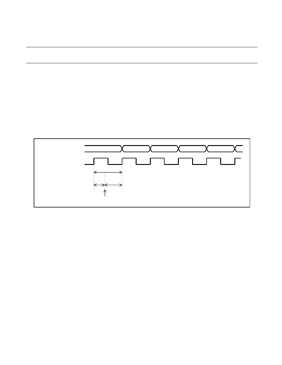
The start of the 8/16-bit capture timer/counter by a program is asynchronous with the start of the counter
incremented by the selected count clock, and therefore, the error (a time difference) continues until the
counter value matches the set data. Such a time difference may shorten the total count duration by a
maximum of one count clock cycle. Figure 8.10-1 shows the error (a time difference) that prolongs the
actual start of count operation.
Figure 8.10-1 Error Occurring until the Count Operation is Started
●
Using only timer 0 in 8-bit mode
When using only timer 0 of the 8/16-bit capture timer/counter in the 8-bit mode, set a value other than 111
B
in the count clock selection bits (TCS12, TCS11, TCS10) of the timer 1 control register (TCR1). Using
timer 0 without setting 111
B
results in a malfunction.
●
Note on setting by program
When using the 8/16-bit capture timer/counter in the 16-bit mode, set the count clock selection bits
(TCS12, TCS11, TCS10) of TCR1 to 111
B
.
Before using the counter values when the counter is in operation with 16-bit mode, be sure to read the
counter values twice and confirm that the values are valid.
Even if square wave output is initialized when the timer is in operation (TCR0: TSTR0 = 1), the output
value is not modified. The output state is initialized when the timer operation stops.
When the interrupt request flag bits (TCCR: CPIF, TCR0: TIF0, TCR1: TIF1) are "1" and the interrupt
request enable bits are allowed (TCCR: CPIEN, TCR0: T0IEN, and TCR1: T1IEN = 1), return from an
interrupt is impossible. In this case, clear the interrupt request flag bits (TCCR: CFCLR = 1, TCR0: TFCR0 =
1, and TCR1: TFCR1 = 1).
4
3
2
1
0
Counter value
Count clock
1 cycle
Error
Count 0
cycle
Counter start