Operation in standby mode and at halfway stop – FUJITSU F2MC-8L F202RA User Manual
Page 213
197
CHAPTER 8 8/16-BIT CAPTURE TIMER/COUNTER
8.9
8/16-bit Capture Timer/Counter Operation in Each Mode
This section describes the operation of the 8/16-bit capture timer/counter when it
switches to the sleep or stop mode or when a halfway stop request is issued during the
operation of the interval timer or counter function.
■
Operation in Standby Mode and at Halfway Stop
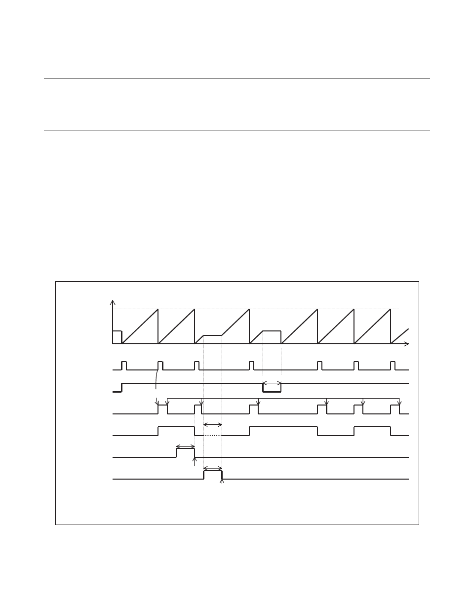
Figure 8.9-1 shows the counter value states if the 8/16-bit capture timer/counter switches to the sleep or
stop mode or when a halfway stop request is issued when the interval timer or counter function is in
operation (at timer 0 operation).
When the counter switches to the stop mode, it retains the value and stops. If the stop mode is released by
an external interrupt, the counter starts its operation at the retained value, and so the first interval time and
external clock count are incorrect. When the stop mode is released, the 8/16-bit capture timer/counter must
be initialized.
When the counter is temporarily stopped (TSTR0 = 0), it retains its value and stops. If the subsequent
operation is continued (TSTR0 = 1), the count value is cleared and the counter is restarted.
Figure 8.9-1 Counter Operation in Standby Mode and at Halfway Stop
0000
H
Co
u
nter v
a
l
u
e
V
a
l
u
e
s
et in d
a
t
a
regi
s
ter
Co
u
nter cle
a
r
S
t
a
rt
M
a
tch
M
a
tch
M
a
tch
M
a
tch
M
a
tch
Time
T
S
TR0
b
it
Cle
a
r
b
y progr
a
m
Tempor
a
ry
s
top
TIF0
b
it
TO pin
S
leep
*
S
LP
b
it
(
S
TBC regi
s
ter)
S
leep rele
as
e
b
y IRQ
3
S
top
S
TP
b
it
(
S
TBC regi
s
ter)
Extern
a
l interr
u
pt
*:
When the pin
s
t
a
te
s
pecific
a
tion
b
it (
S
PL) of the
s
t
a
nd
b
y control regi
s
ter (
S
TBC) i
s
"1"
a
nd the TO pin i
s
not
p
u
lled
u
p, the TO pin in the
s
top mode
b
ecome
s
Hi-Z. When the pin
s
t
a
te
s
pecific
a
tion
b
it (
S
PL) i
s
"0", the v
a
l
u
e
immedi
a
tely
b
efore the
8
/16-
b
it c
a
pt
u
re timer/co
u
nter
s
witche
s
to the
s
top mode i
s
ret
a
ined.