1) electronic gear ratio, 2) electronic gear ratio setting examples, Encoder resolution – Yaskawa Σ-V Series AC Servo Drives Rotational Motor MECHATROLINK-III User Manual
Page 86
4.4 Trial Operation
4-21
4
Op
er
at
io
n
(1) Electronic Gear Ratio
Set the electronic gear ratio using Pn20E and Pn210.
If the gear ratio of the servomotor and the load shaft is given as n/m where m is the rotation of the servomotor
and n is the rotation of the load shaft,
Encoder Resolution
Encoder resolution can be checked with servomotor model designation.
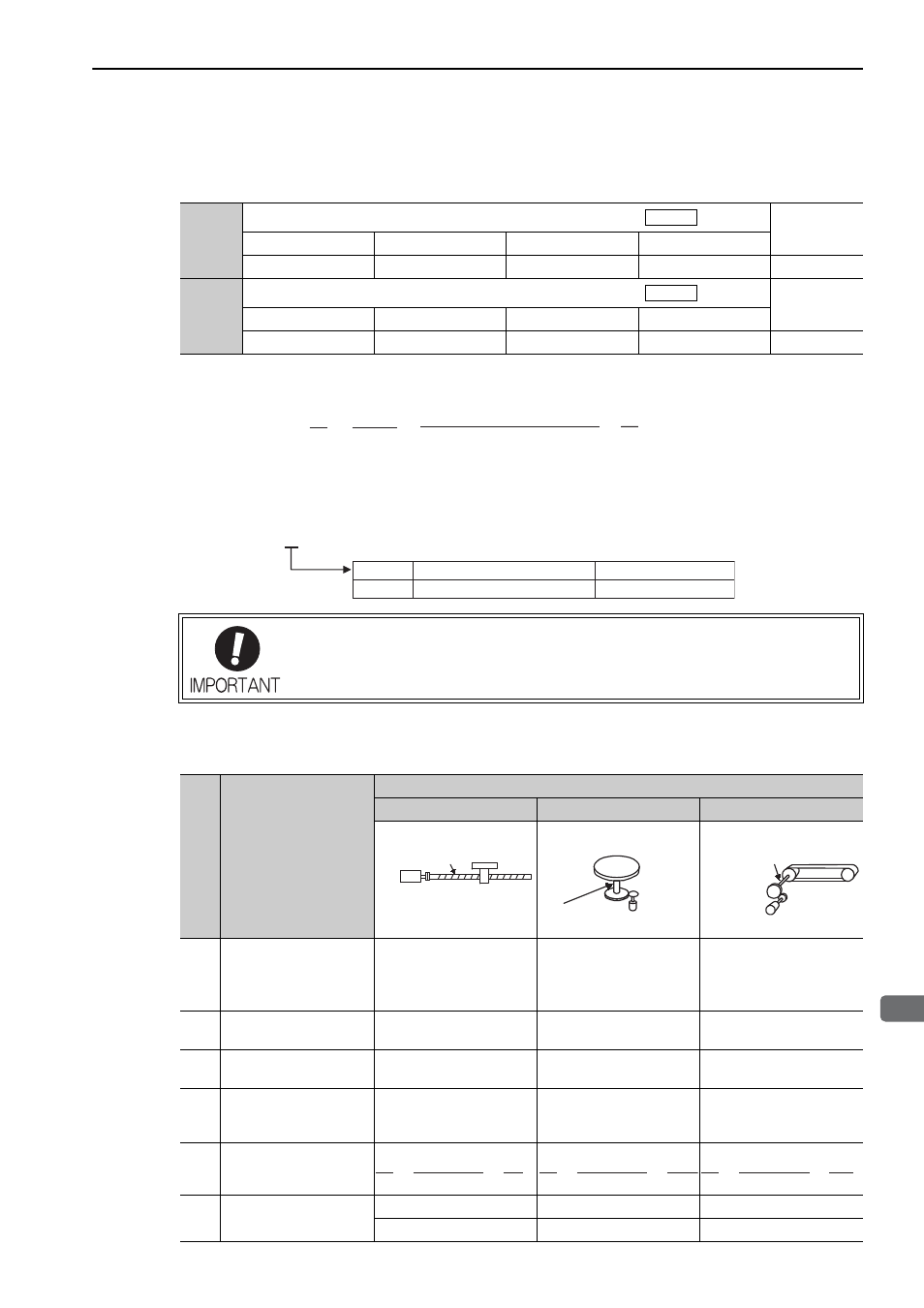
(2) Electronic Gear Ratio Setting Examples
The following examples show electronic gear ratio settings for different load configurations.
Pn20E
Electronic Gear Ratio (Numerator)
Classification
Setting Range
Setting Unit
Factory Setting
When Enabled
1 to 1073741824
1
1
After restart
Setup
Pn210
Electronic Gear Ratio (Denominator)
Classification
Setting Range
Setting Unit
Factory Setting
When Enabled
1 to 1073741824
1
1
After restart
Setup
Position
Position
Electronic gear ratio:
=
A
B
Pn210
Pn20E
=
n
m
Encoder resolution
Travel distance per load
shaft revolution (reference units)
×
Electronic gear ratio setting range: 0.001
≤
Electronic gear ratio (B/A)
≤
4000
If the electronic gear ratio is outside this range, a parameter setting error 1 (A.040) will
be output.
Symbol Specification Encoder
Resolutions
SGMMV
2
17-bit absolute
131072
Step
Operation
Load Configuration
Ball Screw
Disc Table
Belt and Pulley
1
Check machine specifica-
tions.
• Ball screw pitch: 6 mm
• Gear ratio: 1/1
Rotation angle per revolu-
tion: 360
°
Gear ratio: 1/100
Pulley diameter: 100 mm
(pulley circumference: 314
mm)
• Gear ratio: 1/50
2
Check the encoder reso-
lution.
131072 (17-bit)
131072 (17-bit)
131072 (17-bit)
3
Determine the reference
unit used.
Reference unit: 0.001 mm
(1
μ
m)
Reference unit: 0.01
°
Reference unit: 0.005 mm
(5
μ
m)
4
Calculate the travel dis-
tance per load shaft revo-
lution. (Reference unit)
6 mm/0.001 mm=6000
360
°
/0.01
°
=36000
314 mm/0.005 mm=62800
5
Calculate the electronic
gear ratio.
6
Set parameters.
Pn20E: 131072
Pn20E: 13107200
Pn20E: 6553600
Pn210: 6000
Pn210: 36000
Pn210: 62800
Ball screw
pitch: 6 mm
17-bit encoder
Load shaft
Reference unit: 0.001 mm
17-bit encoder
Load shaft
Reference unit: 0.01
°
Gear ratio:
1/100
Load shaft
Gear ratio
1/50
Reference unit: 0.005 mm
Pulley diameter:
100 mm
17-bit encoder
131072
6000
1
1
=
B
A
B
A
131072
36000
100
1
=
B
A
131072
62800
50
1
=